The Working Principles of Electrical Transformers in Power System
Published: Author: Kampa
What do street lights, big industrial motors, data centers, and sports arenas share? They all depend on a steady, high supply of electricity.
However, powering this equipment is not as simple as tapping straight into overhead lines. The electricity in transmission lines is at very high voltage, which is useful for moving power over long distances, not for direct use in everyday systems. Before it can be used, the voltage must be adjusted by a Electrical Transformers so the power is at a safe, suitable level.
Most people can recognize a transformer when they see one, but far fewer understand what it actually does. If you are planning a project that involves buying or installing a transformer, it helps to know its basic role and inner workings. This overview explains what a transformer is, why it is necessary, how it operates, and the main parts that make it up.
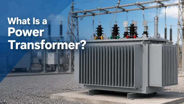
What is a Transformer?
Put simply, a transformer is an electrical device that takes an input voltage and changes it to a different output voltage. That change can go in either direction: the transformer can raise the voltage (step it up) or lower it (step it down).
The transformers we most commonly encounter are Electrical Transformers—the devices that reduce voltage to levels suitable for use in homes, factories, shopping centers, airports, and other residential or commercial environments. Since electrical systems differ greatly across distribution networks, multiple transformer types have been developed, each tailored to a specific application.
Electricity and Why We Need to Transform It Electrical Transformers
Electric power has two main parts: current and voltage.
Current is how fast electrical energy flows, measured in amps.
Voltage is the force that pushes that energy, measured in volts.
You can picture electricity like water moving through a pipe. Current is like how much water flows. Voltage is like the water pressure. To move water from a city reservoir to homes, offices, and factories, you need large pipes and high pressure. The main water lines are designed for huge flow rates, pushed along by strong pressure.
If you connected one of those high-pressure city mains straight to your kitchen faucet, it would explode the moment you opened it, and your house would flood. To make the water usable, the pressure from the main line has to be reduced with pressure regulators. Once that pressure is lowered, the water becomes safe and practical for showers, dishwashing, garden hoses, and everyday tasks at home or work.
Voltage Transformers do a similar job for electricity. Power lines can carry more than 300,000 volts, which is an enormous amount of electrical “pressure.” To make this power safe and useful, transformers reduce the voltage at or near the point where it will be used. Transformers that lower voltage like this are called step-down transformers.
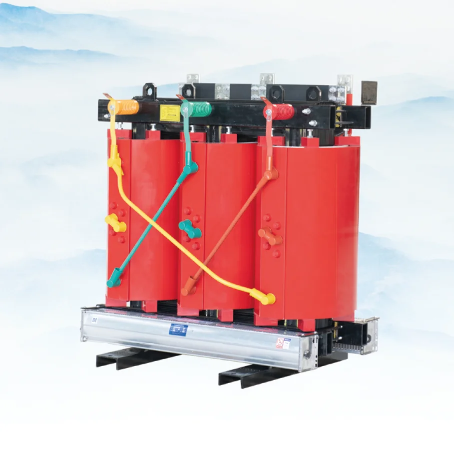
They come in many sizes: huge substation transformers in utility yards, large green padmount transformers on concrete pads near buildings, and smaller polemount transformers on top of power poles.
Factories, large buildings, and other commercial or industrial sites typically use big transformers that supply three-phase voltages such as 480 or 208 volts. Houses and small shops usually rely on smaller single-phase transformers that provide 120/240-volt single-phase power. In what follows, the focus is on three-phase distribution transformers.
How Do Transformers Work?
Electrical Transformers work based on the law of energy conservation: energy cannot be created or destroyed, only converted from one form to another. This means a transformer does not generate electrical energy; it only adjusts the voltage level so that the same power can be used safely and efficiently for different applications.
The key physical principle behind a transformer is electromagnetic induction. Inside a transformer, this principle allows energy to be transferred from one circuit to another through a changing magnetic field, without the two circuits being electrically connected.
Electromagnetic Induction
When an alternating current (AC) flows through a wire (called a conductor), it creates a changing magnetic field around that wire. Because the current is alternating, the magnetic field is also constantly changing in strength and direction.
If you place a second conductor close to the first one, inside this changing magnetic field, the moving magnetic flux lines cut across the second conductor. According to Faraday’s law of electromagnetic induction, this changing magnetic flux induces a voltage (and thus a current, if the circuit is closed) in the second conductor.
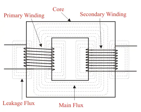
To make this effect strong and useful, transformers do not use just straight wires, but wind the conductors into coils (windings). There are two main windings:
Primary winding: connected to the input voltage source
Secondary winding: connected to the output (load)
Both windings are wrapped around a common magnetic core so that the magnetic flux produced by the primary passes efficiently through the secondary.
By choosing different numbers of turns (loops) in the primary and secondary windings, a transformer can step voltage up or down:
If the primary winding has more turns than the secondary, the voltage in the secondary will be lower than the primary (step-down transformer).
If the primary winding has fewer turns than the secondary, the voltage in the secondary will be higher than the primary (step-up transformer).
In the example you gave, if the coil with more loops is energized, it establishes a changing magnetic field in the core. This changing field links to the coil with fewer loops, inducing a lower voltage in that shorter coil. The ratio of voltages is approximately equal to the ratio of the number of turns:
where V is voltage and N is the number of turns in each winding.
How Does a Transformer Coil Work?
A transformer coil works by using two separate windings—primary and secondary—wrapped around a shared metal core to transfer energy through a changing magnetic field.
Basic coil structure
The first winding that receives incoming electrical power is called the primary coil. The second winding, where voltage is induced and then sent to the load, is called the secondary coil. Both coils (also called windings) are made from conductive metal, usually copper or aluminum, and are wound around a common iron or steel core to concentrate and guide the magnetic flux. As the alternating current in the primary changes, the core magnetizes and demagnetizes, physically expanding and contracting slightly; this mechanical vibration is what produces the familiar humming or buzzing of a transformer.
Each complete loop of wire around the core is called a “turn.”
Turns ratio and voltage
The key principle is that the turns ratio between the primary and secondary coils determines the voltage ratio between input and output. In ideal form:VsecondaryVprimary=NsecondaryNprimary
where Vprimary and Vsecondary are the primary and secondary voltages, and Nprimary and Nsecondary are the corresponding numbers of turns.
So, if the turns ratio is 25:1, the voltage ratio is also 25:1. Designers choose the exact number of turns on each coil to obtain the required output voltage. For example, a transformer with a 25:1 turns ratio can convert 12,000 volts on the primary side down to 480 volts on the secondary side (12,000 ÷ 25 = 480).
Learn what a dry type power transformer is, how to connect and size it, and what really drives Electrical Transformers and price for buyers.
For three-phase transformers, the individual coils for each phase are interconnected in specific patterns. The most common configurations are:
Delta (Δ): windings are connected end-to-end in a closed loop
Wye (Y): one end of each winding is tied to a common neutral point
By choosing delta, wye, or combinations (e.g., delta–wye), engineers control phase relationships, available line voltages, and grounding behavior in three-phase systems.
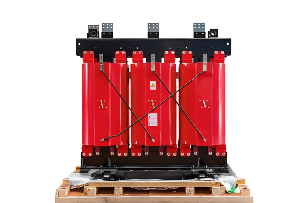
Parts of a Transformer
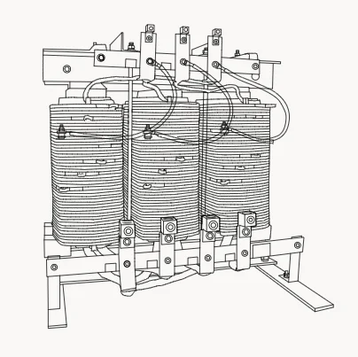
Transformers come in many designs—such as unit substation, polemount, medium-voltage dry-type, and low-voltage dry-type units—but they share a common set of main components. Here we will look at the key parts typically found in an oil-filled padmount transformer.
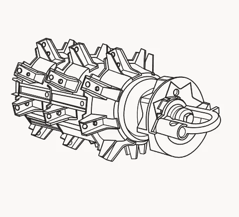
Core
The core is built from thin, stacked sheets of electrical steel, laminated to reduce losses. The windings are placed around this core, and when current flows in the windings it creates a magnetic field that is guided by the core to couple the primary and secondary efficiently.
Coils
The coils are the windings of aluminum or copper wrapped around the core. They consist of a primary winding, which is connected to the incoming utility voltage, and a secondary winding, which delivers a different voltage level—either stepped up or stepped down depending on the design.
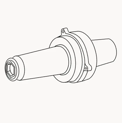
Bushings
Transformer bushings are insulated terminals that let conductors pass through the steel tank wall without touching it electrically. High‑voltage bushings connect the transformer to the supply, while low‑voltage bushings connect to the load side.
Fuses
Fuses protect the transformer and downstream equipment from faults and overloads by interrupting excessive current. When the current or temperature exceeds the fuse rating, the internal fuse element melts, opening the circuit and disconnecting the transformer from the system.
Voltage Adjustment Taps
Voltage adjustment taps are connection points on the winding that allow small changes in the effective number of turns. By changing the tap position with a tap changer, sections of the primary winding are added or removed, slightly shifting the turns ratio so the secondary voltage can be kept within the correct range even when the primary voltage is high or low.
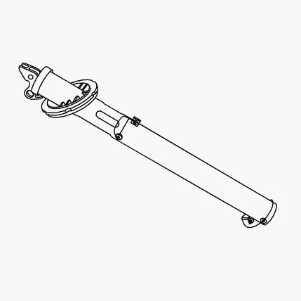
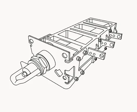
Load Break Switches
A transformer load break switch (LBOR) is a rotary disconnect switch that serves as the transformer’s on/off control. It is designed so that operators can make or break the rated current while the transformer is energized, safely isolating it from the power grid under load conditions.
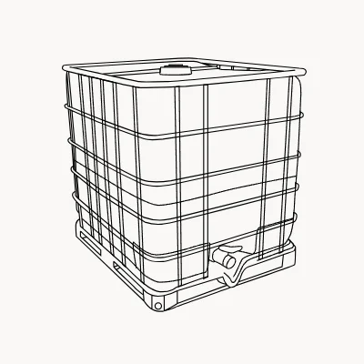
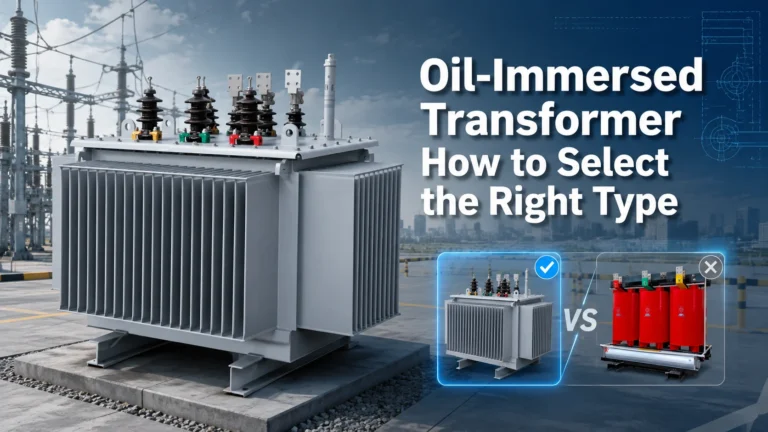
Fluid
In liquid‑filled units, insulating fluid (often mineral oil or a biodegradable alternative) fills the tank around the core and coils. This fluid provides both cooling—by carrying heat to the tank walls and radiators—and electrical insulation between energized parts and the grounded tank.
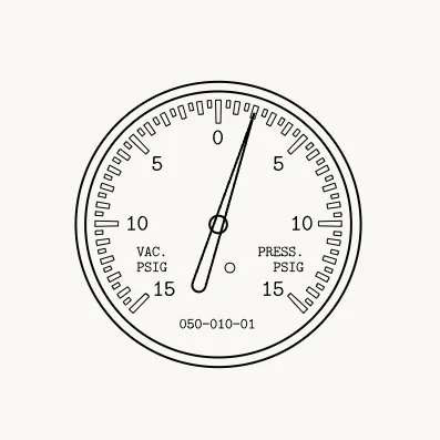
Gauges
Gauges and indicators monitor key operating parameters such as oil level, oil temperature, and tank pressure or vacuum. Larger transformers may include more advanced monitoring instruments, alarms, and sensors for detailed condition tracking.
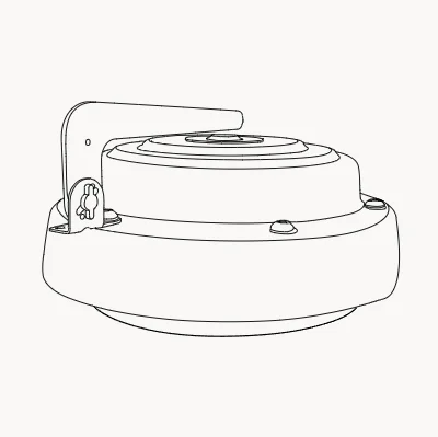
Pressure Relief Device
If an internal fault or overheating causes gas and pressure to build up inside the tank, a pressure relief device opens to vent the excess pressure. This controlled venting prevents the tank from reaching a critical pressure that could cause deformation or rupture.
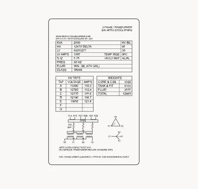
Nameplate
The nameplate is a durable label that lists the transformer’s ratings and key data. Typical information includes kVA rating, primary and secondary voltage ratings, phase, winding diagram, vector group, cooling class, impedance, and other important operating details.
The basic idea behind Dry-type Power Transformers is simple: they accept electrical power at one voltage, convert it to another voltage level, and then deliver that adjusted power so it can run almost any kind of electrical load. In doing so, they make it possible to match the voltage on the grid to the specific requirements of equipment and systems, from low‑voltage electronics to high‑power industrial machines.
Because of this, transformers are embedded in nearly every part of modern infrastructure. They help distribute power to homes and offices, support industrial production, keep data centers online, and even make things like electric ovens, HVAC equipment, and field-heating systems practical and safe to operate. In short, everyday activities—from baking and grooming to running stadium lighting and server farms—depend on transformers quietly doing their job in the background.
Whether you are just starting to learn about Electrical Transformers or have worked with them for some time, understanding their basic principle—changing voltage efficiently through electromagnetic induction—gives you a clearer picture of how the entire power system functions.
FAQ
What does a transformer do?
A Electrical Transformers changes electrical voltage from one level to another so power can be used safely and efficiently by different devices.
Why do we need to change voltage?
High voltage is good for long‑distance transmission, but it must be reduced to safer levels for homes, businesses, and equipment.
What are current and voltage in simple terms?
Current is the flow rate of electricity (like water flow), and voltage is the electrical “pressure” that pushes it.
What is a step‑down transformer?
A step‑down transformer lowers voltage from a higher level (like power lines) to a lower level suitable for end users.
How does a transformer work in principle?
It uses electromagnetic induction: a changing magnetic field in the primary coil induces a voltage in the secondary coil.
What are primary and secondary coils?
The primary coil is connected to the input supply, and the secondary coil delivers the transformed output voltage.
What is the turns ratio?
The turns ratio is the ratio of coil turns (primary to secondary); it directly sets the voltage ratio between input and output.
What is a three‑phase transformer?
A three‑phase transformer supplies three‑phase power (common in industry) and often uses delta or wye coil connections.
What is the core of a transformer for?
The core guides the magnetic flux between windings, improving energy transfer and efficiency.
What is a load break switch?
It is a manual switch that can safely connect or disconnect a Electrical Transformers from the grid even while it is carrying load.
Where are Electrical Transformers used in daily life?
They appear in power grids, buildings, factories, data centers, and many devices that need specific voltage levels.
A power transformer is an electrical device that transfers electrical energy from one circuit to another through electromagnetic induction, changing voltage and current levels without changing frequency.