


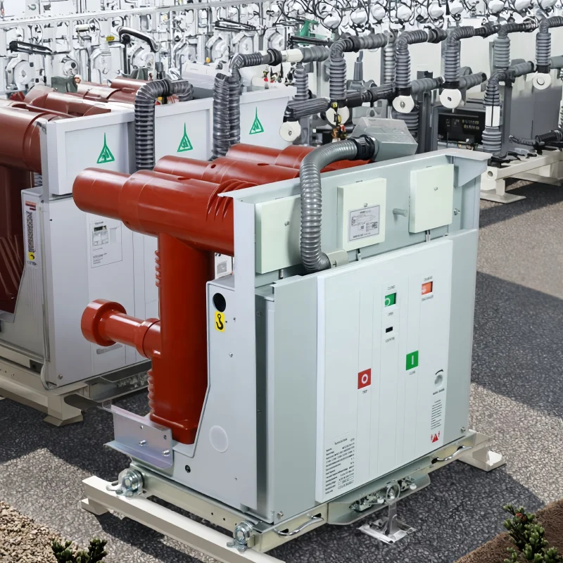

Description
VZF(R) 12kV Series at a Glance
The VZF(R) 12kV switch-fuse combination pairs a vacuum load break switch with a high-breaking-capacity fuse inside one indoor air-insulated unit. Two builds of the VZF(R) 12kV switch-fuse combination come from the same frame: the VZF-12/T630-20 load switch rated 630 A, and the VZFR-12/T125-50 combination rated 125 A with a 50 kA fuse.
Which one you need depends on what sits downstream. A load switch interrupts load current but not fault current, so it is used where protection is provided elsewhere. The fuse combination carries its own short-circuit protection, which makes it the usual choice for a transformer feeder in a ring main unit or a compact secondary substation.
Reading VZF and VZFR
| Element | Meaning | What it settles |
|---|---|---|
| V | Vacuum interrupter | Sealed arc-quenching chamber, no SF6 |
| Z | Load break switch (负荷开关) | Switches load current, not fault current |
| F | With fuse | Short-circuit protection built into the unit |
| R | Fuse combination variant | Distinguishes the combination from the plain switch |
| 12 | Voltage class in kV | 12 kV class, 42/75 kV insulation |
| T630-20 | 630 A, 20 kA short-time withstand | The load-switch build |
| T125-50 | 125 A fuse, 50 kA breaking | The fuse-combination build |
Note that the two suffixes describe different things. T630-20 is a current and withstand rating, while T125-50 is a fuse current and the breaking capacity of that fuse. They are not comparable numbers and should not be read as one unit being stronger than the other.
Ratings Compared
| Parameter | VZF-12/T630-20 | VZFR-12/T125-50 |
|---|---|---|
| Rated voltage | 12 kV | 12 kV |
| Power-frequency withstand | 42 kV | 42 kV |
| Lightning impulse withstand | 75 kV | 75 kV |
| Rated current | 630 A | 125 A fuse |
| Short-circuit breaking | Provided by upstream protection | 50 kA through the fuse |
| Short-time withstand, 20 kA | Yes | Not applicable |
The asymmetry is the point of the series. The 630 A switch carries fault current for the short-time duration and relies on a breaker upstream to clear it. The 125 A combination clears the fault itself, but only up to the fuse rating, and the fuse is consumed in the process.
Mechanical Data
| Contact gap | 9 ± 1 mm |
|---|---|
| Contact-pressure spring travel | 4 ± 1 mm |
| Phase centre distance | 210 / 275 mm |
| Opening / closing time difference between phases | ≤ 2 ms |
| Average closing speed | 0.4 – 0.8 m/s |
| Average opening speed | 1.0 – 1.4 m/s |
| Closing time | ≤ 60 ms |
| Opening time | ≤ 30 ms |
| Main-circuit resistance | ≤ 250 mΩ |
The 9 mm contact gap is wide for a 12 kV device, and the phase distance comes in two options. Both matter to the cubicle designer: the gap sets the interrupter travel and the mechanism energy, while the 210 or 275 mm phase spacing decides whether the unit drops into an existing busbar arrangement or requires a new one.
When the Load Switch Alone Is Enough
The 630 A build suits circuits where fault current is already cleared upstream and the switch only has to make and break load.
- Feeder sectionalising in a board that has a breaker on the incomer.
- Isolation for maintenance where a visible break and load-breaking capability are required but fault interruption is not.
- Busbar sectioning between two protected sections.
Its 20 kA short-time withstand means the unit survives the fault while the upstream device clears it. Check that figure against the fault level at the installation point, because a busbar rated above 20 kA puts the switch outside its withstand.
When the Fuse Combination Is the Right Choice
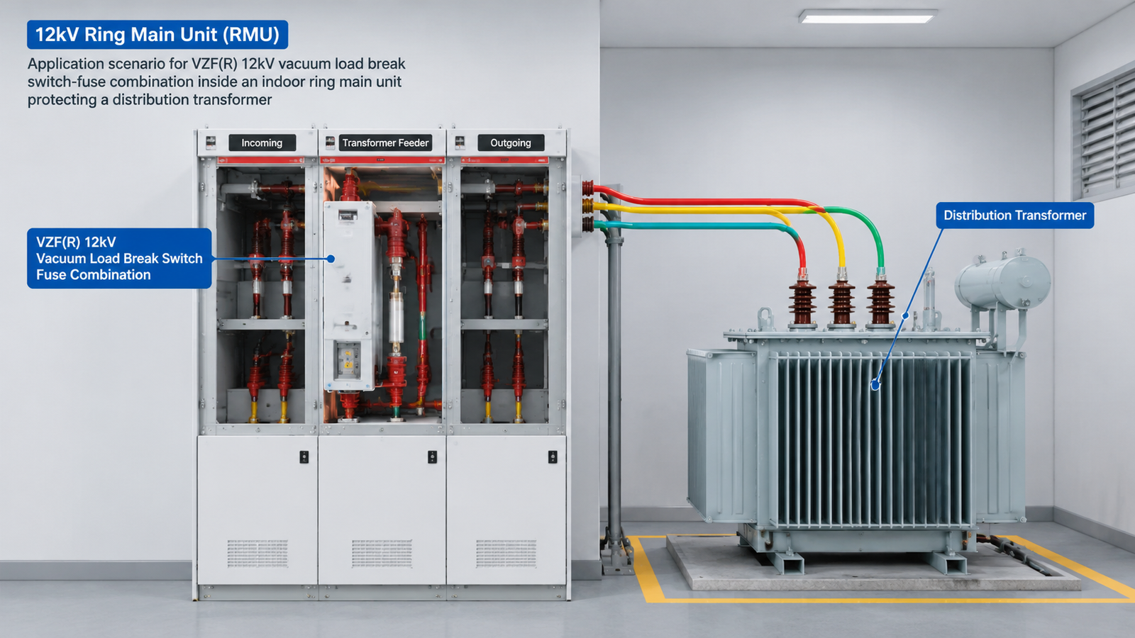
The 125 A build of the VZF(R) 12kV switch-fuse combination is the standard answer for a transformer feeder in a ring main unit, a compact secondary substation, or a wind-farm collector circuit.
- Transformer protection. The fuse clears a transformer primary fault without needing a breaker and a relay in the panel.
- Compact installations. One unit replaces a breaker plus a relay plus current transformers, which is what makes the small footprint possible.
- Radial feeders with a defined fault level. The 50 kA fuse breaking capacity covers most 12 kV distribution boards.
The trade is recovery time. A blown fuse means replacing the fuse and finding out why it blew, so this is not the device for a circuit that trips often.
Sizing the Fuse to the Transformer
The fuse has to satisfy three conditions at once, and a rating chosen on transformer current alone will usually fail one of them.
- Above the transformer’s rated current with margin, so the fuse does not age out under normal load.
- Above the magnetising inrush, which reaches roughly 8 to 12 times rated current for around 0.1 second when the transformer is energised. A fuse sized too close to rated current will blow on energisation.
- Below the transformer’s short-circuit withstand, so the fuse clears before the winding is damaged.
The 125 A fuse in this build typically covers transformers in the 1,000 to 1,600 kVA range at 12 kV, but the inrush check decides it rather than the capacity figure. Send the transformer rating, the percentage impedance and the supply fault level, and the fuse value is confirmed against all three.
One more point that matters for operation: a fuse blowing on one phase leaves the other two energised. The panel should have phase-failure protection, otherwise the transformer runs single-phased and overheats.
Phase Spacing and Cubicle Fit
The VZF(R) 12kV switch-fuse combination is offered at 210 mm and 275 mm phase centre distance. The wider option suits boards built to the larger clearance convention, and the narrower one fits compact ring main units.
Because the two options are not interchangeable on site, confirm the phase spacing of the existing cubicle before ordering, or send the panel drawing. A unit built at the wrong spacing cannot be adapted with brackets; the busbar connections will not line up and the clearances will be wrong.
Interlocks and Operating Sequence
The VZF(R) 12kV switch-fuse combination is normally interlocked so that the fuse compartment cannot be opened while the switch is closed, and the switch cannot be closed with the fuse compartment open. That interlock is part of the safety case for the panel and should be specified explicitly.
State the required operating sequence with the inquiry: whether the unit is operated manually from the front, whether remote operation is needed, and whether the earth switch is part of the same interlock chain. These change the accessory set rather than the interrupting rating.
When a Different Device Fits Better
- Frequent fault interruption. A vacuum circuit breaker re-closes without replacing a fuse. For a feeder that trips regularly, the CKG3 12 kV contactor with upstream protection, or a breaker, is the better fit.
- Motor starting duty. Motor circuits need a contactor rated for starting current, not a load break switch. See the JCZ5 vacuum contactor range.
- Loads above 125 A with fuse protection. The 630 A switch plus a separate protection scheme is the alternative.
All switching devices are listed under vacuum contactor series and the circuit breaker category.
Service Conditions
Indoor installation in air-insulated switchgear, at altitudes up to 1,000 m and ambient from -25 °C to +40 °C. Above 1,000 m the external insulation needs correction, and above 40 °C the current rating is derated.
Pollution level belongs in the inquiry. The creepage is fixed by the casting and the phase spacing, so a unit built for a clean switchroom will not perform in a coastal or cement-plant environment without a different specification.
Standards and Routine Tests
Routine tests on every unit cover power-frequency withstand at 42 kV, main-circuit resistance against the 250 mΩ limit, contact gap and spring travel against the published tolerances, and a mechanical operation check including the phase-synchronism figure of 2 ms or better.
Type test reports covering temperature rise, short-time withstand and making/breaking capacity are available for project documentation.
Manufacturer Supply, OEM and Wholesale
Both builds of the VZF(R) 12kV switch-fuse combination are supplied direct. Switchgear builders order against a frozen phase spacing and interlock specification under OEM or private-label marking; distributors hold a standing specification for repeat supply; project buyers receive drawings and test reports for consultant approval.
Because the interlock chain and the phase spacing are built to order, non-standard panel arrangements are quotable rather than declined.
Price, MOQ and Lead Time
- MOQ. Single units for standard configurations. Custom phase spacing, interlock arrangements and private-label marking carry a higher minimum.
- Price drivers. Build (load switch or fuse combination), phase spacing, interlock complexity, earth switch requirement and quantity.
- Lead time. Confirmed against the production schedule at order.
- Payment. Deposit with balance against the bill of lading copy; letter of credit for project quantities.
What to Send With Your Inquiry
- Required build: VZF load switch or VZFR fuse combination
- System voltage and continuous current
- Transformer rating and impedance, if the fuse is to be sized by us
- Fault level at the installation point
- Existing phase spacing, 210 mm or 275 mm
- Interlock and earth switch requirements
- Manual or remote operation
- Quantity, destination port and required delivery date
Send those through the quote form on this page. The phase spacing and the interlock chain are the two items that most often need a second round, because neither can be changed after the unit is built.
FAQ
What is the difference between VZF and VZFR?
Which build suits a transformer feeder?
How is the fuse sized?
What happens if one fuse blows?
Can the phase spacing be changed after manufacture?
What is the MOQ and lead time?
Request Quote
Tell us your specifications, quantity, or application scenario and we will reply with a tailored quote.