
Description
JDZX9-35 at a Glance
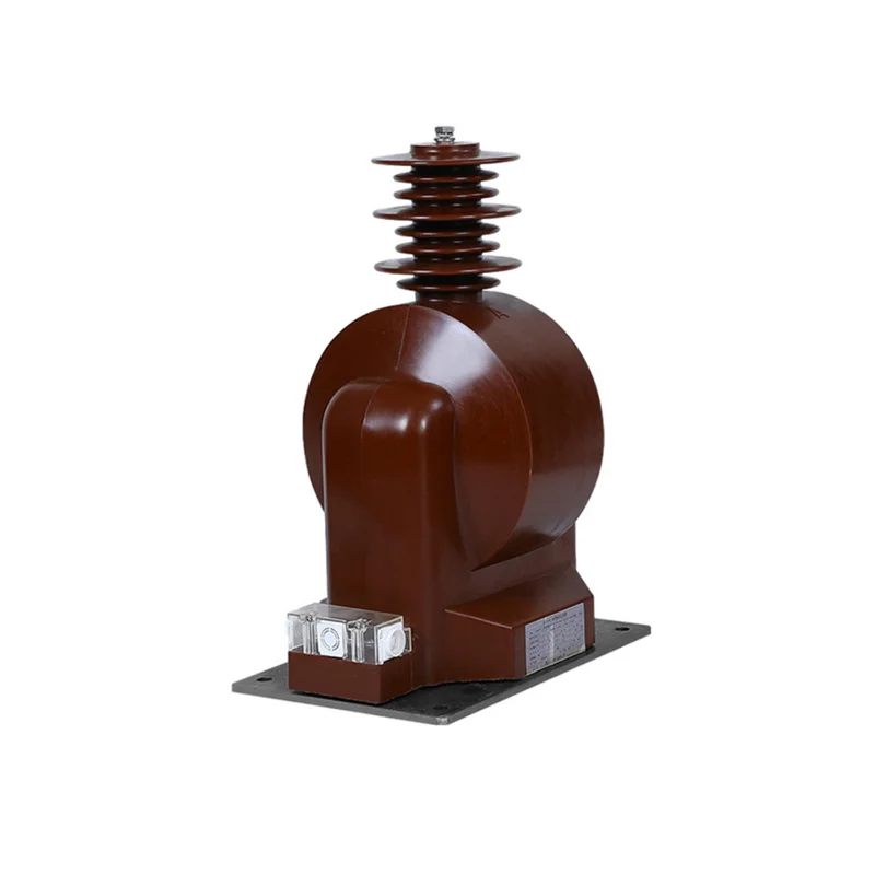
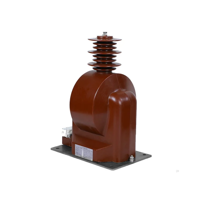
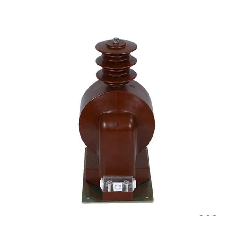
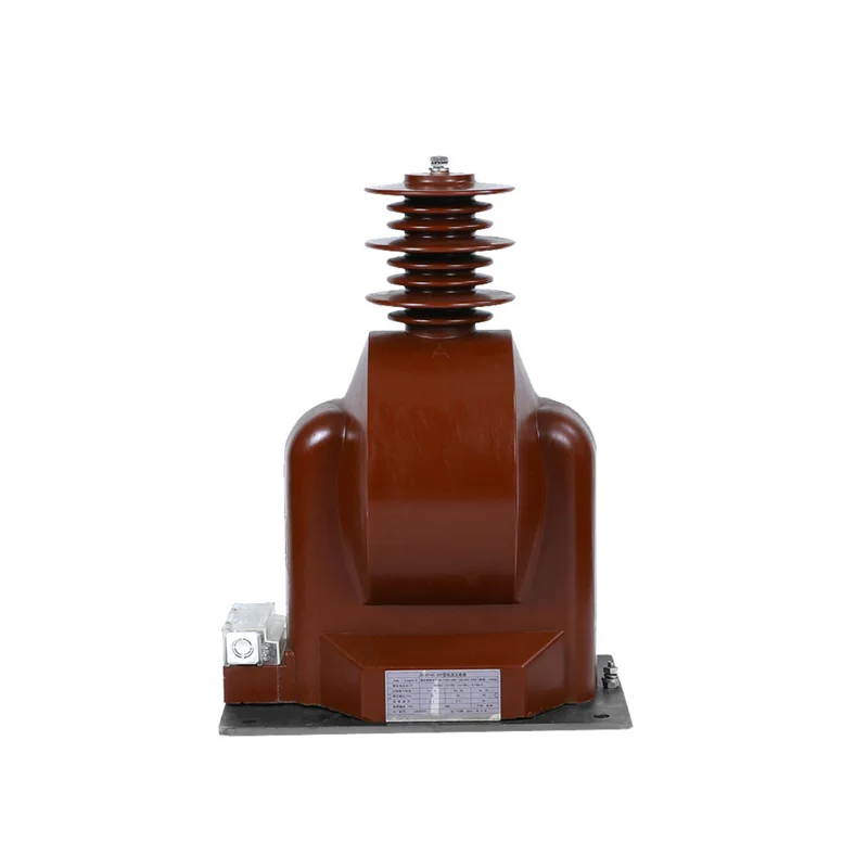
The JDZX9 35kV voltage transformer is a single-phase, semi-insulated epoxy-resin cast unit for indoor 35 kV switchgear, wound for phase-to-earth voltage measurement with a third winding dedicated to residual voltage. Three units form a YO/YO/△ set that gives a substation both its phase voltages and its earth-fault signal from one installation.
The voltage ratio of the JDZX9 35kV voltage transformer is 35/√3 / 0.1/√3 / 0.1/3 kV, so the primary and main secondary are phase-to-earth quantities and the third winding produces the zero-sequence voltage that drives an earth-fault relay. It is the standard arrangement for a 35 kV system with a grounded neutral, not a general-purpose metering transformer.
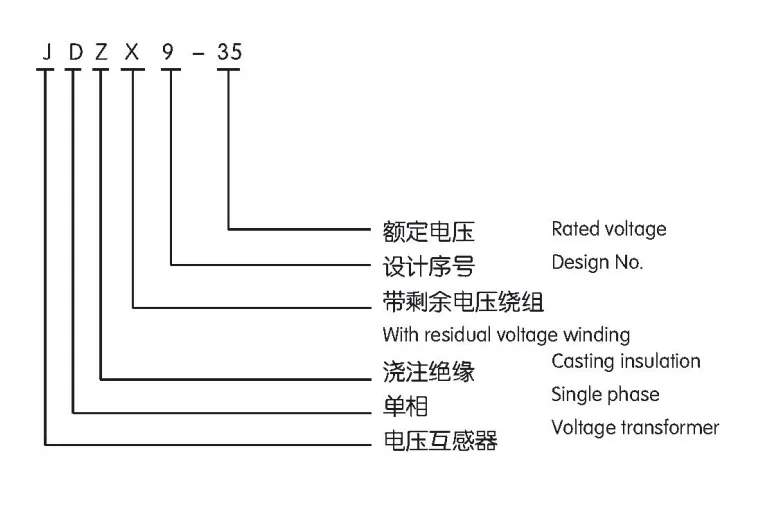
Reading the Designation
| Element | Meaning | What it decides |
|---|---|---|
| J | Voltage transformer (电压互感器) | PT, not a current transformer |
| D | Single-phase (单相) | One unit per phase, three per set |
| Z | Cast insulation (浇注绝缘) | Epoxy body, no oil |
| X | Semi-insulated | One primary end designed for the grounded side |
| F | With residual voltage winding | Third winding for open-delta connection |
| 9 | Design sequence | Frame family |
| 35 | Voltage class in kV | 35 kV system, 40.5 kV highest voltage |
The Three Windings and What Each Does
This is the part that separates the JDZX9 35kV voltage transformer from a two-winding PT, and it is worth being precise about.
| Winding | Rated voltage | Function |
|---|---|---|
| Primary | 35/√3 kV | Connected phase to earth |
| Main secondary | 0.1/√3 kV | Phase voltage for meters, transducers and protection relays |
| Residual (tertiary) | 0.1/3 kV | Connected in open delta, outputs zero-sequence voltage on an earth fault |
The 0.1/3 kV figure is easy to misread. It is one third of 0.1 kV, or about 33.3 V per phase, chosen so that three windings in open delta produce 100 V when one phase goes to earth. That 100 V is the standard input for an earth-fault relay, which is why the figure is fixed by convention rather than by the manufacturer.
Connection Group YO/YO/△-12-11
Three single-phase units are connected as YO/YO/△-12-11: primary star with neutral earthed, main secondary star with neutral earthed, and the residual windings in open delta.
In normal operation the three residual voltages sum to zero, so the open-delta terminals sit at close to zero volts. When one phase faults to earth, that phase’s voltage collapses and the other two rise to line-to-line value. The vector sum is no longer zero, and the open delta produces a voltage that rises to the rated 100 V for a solid earth fault on the affected phase.
Two practical consequences follow. The relay must be set to ignore the small standing voltage that appears from system unbalance, otherwise it trips on normal conditions. And the three units of a set should be matched, because unequal ratios across the three phases produce a standing zero-sequence voltage even with a healthy system.
Ratings and Accuracy Pairs
| Type | Voltage ratio (kV) | Accuracy combination | Rated output (VA) | Limit output (VA) | Insulation level (kV) |
|---|---|---|---|---|---|
| JDZX9-35 | 35/√3 / 0.1/√3 / 0.1/3 | 0.2 / 6P | 30 / 100 | 600 | 40.5 / 95 / 185 |
| JDZX9-35 | 35/√3 / 0.1/√3 / 0.1/3 | 0.5 / 6P | 80 / 100 | ||
| JDZXF9-35 | 35/√3 / 0.1/√3 / 0.1/√3 / 0.1/3 | 0.2 / 0.5 / 6P | 30 / 50 / 100 |
The JDZXF9-35 carries four windings: primary, two independent secondary windings and the residual winding. That configuration suits a bay where metering and protection need separate circuits as well as an earth-fault signal, which is common on a utility feeder but unusual on a plant board.
Note that 6P is the protection class on both builds, with 100 VA. There is no 10P option listed, and the metering class tops out at 0.2 rather than 0.2S. Where a load swings very widely, the 0.2S class is preferable, and that is a different frame.
Residual Voltage Winding for Earth Fault Protection
A 35 kV system with a grounded neutral needs earth-fault protection that detects a single phase going to earth. There are two ways to get the signal: three current transformers with a core-balance connection, or three voltage transformers with residual windings. This frame is the second approach.
It is the cheaper of the two for a substation bay, because the voltage transformers are already there for metering. Adding the residual winding to the same casting costs far less than a separate set of core-balance CTs and their wiring.
The limitation is that residual voltage detection is less sensitive than core-balance current detection on a high-impedance earthed system. For a solidly earthed 35 kV network the residual winding is adequate; for a system earthed through a resistor, confirm the relay setting against the expected residual voltage before relying on this method alone.
Semi-Insulated Construction at 35 kV
The X in the model marks semi-insulated construction on the JDZX9 35kV voltage transformer: one end of the primary winding is cast inside the body and the other is designed to sit at or near earth potential. This is the normal arrangement for a phase-to-earth voltage transformer, where the primary is connected between phase and earth and the earthed end does not need full insulation.
It is not interchangeable with a fully insulated unit. Our JDZ9-35 voltage transformer is the fully insulated frame with a 35/0.1 kV ratio for line-to-line metering, and it is a different product rather than a variant of this one. If you need line voltage for metering without earth-fault detection, that is the page to look at.
Installation and Service Conditions
The JDZX9 35kV voltage transformer is installed indoors in metal-clad switchgear, at pollution class II and a load power factor of 0.8 lagging as stated in the published data. Ambient and altitude limits follow the standard indoor envelope; state the site altitude at the inquiry because the external insulation is corrected above 1,000 m.
The unit mounts on a base plate with the primary connected to the busbar and the secondary and residual windings brought out to the terminal box. The three units of a set are installed one per phase, with the residual windings wired in open delta at the relay panel rather than at the transformer.
Standards and Routine Tests
Units are built and tested to GB 20840.3-2013 and the corresponding IEC instrument transformer standard. Routine tests cover power-frequency withstand, insulation resistance, ratio and polarity on each winding, and ratio error and phase displacement at the rated output for the declared accuracy class.
Because the residual winding is part of the accuracy specification, its ratio and polarity are verified as well, not only the main secondary. Type test reports covering temperature rise and impulse withstand are available for project documentation.
When a Different PT Fits Better
- Line-to-line metering without earth-fault detection. The JDZ9-35 fully insulated voltage transformer uses a 35/0.1 kV ratio and a 1,000 VA limit output.
- 10 kV and below. The JDZ10 cast voltage transformer covers those classes.
- Fused construction. Where the primary tap needs its own fuse, see the JDZX18 voltage transformer with fuse.
Manufacturer Supply, OEM and Wholesale
The JDZX9 35kV voltage transformer is supplied direct. Project buyers order three-unit sets matched for ratio and polarity, with test reports and connection diagrams issued for approval; switchgear builders order against a frozen ratio and class specification under OEM or private-label marking; distributors hold a standing specification for repeat supply.
Price, MOQ and Lead Time
- MOQ. Single units, though earth-fault applications usually order in sets of three.
- Price drivers. Accuracy combination, two or three secondary windings, and quantity. The JDZXF9 four-winding build sits above the three-winding JDZX9.
- Lead time. Confirmed against the production schedule at order.
- Payment. Deposit with balance against the bill of lading copy; letter of credit for project quantities.
What to Send With Your Inquiry
- System voltage and earthing method: solidly earthed or impedance earthed
- Voltage ratio required, and whether the residual winding is needed
- Accuracy class and rated output for each winding
- Number of units: three per set for a YO/YO/△ arrangement
- Whether a matched set is required, and how it will be identified
- Pollution level and site altitude
- Quantity, destination port and required delivery date
Send those through the quote form on this page. The earthing method and the winding configuration are what separate this frame from a standard metering PT, so both belong in the first message.
FAQ
What is the residual voltage winding for?
Why is the ratio 35/√3 rather than 35/0.1?
What does 0.1/3 kV mean on the residual winding?
Do I need three units?
Should the three units be matched?
What is the MOQ?
Request Quote
Tell us your specifications, quantity, or application scenario and we will reply with a tailored quote.