


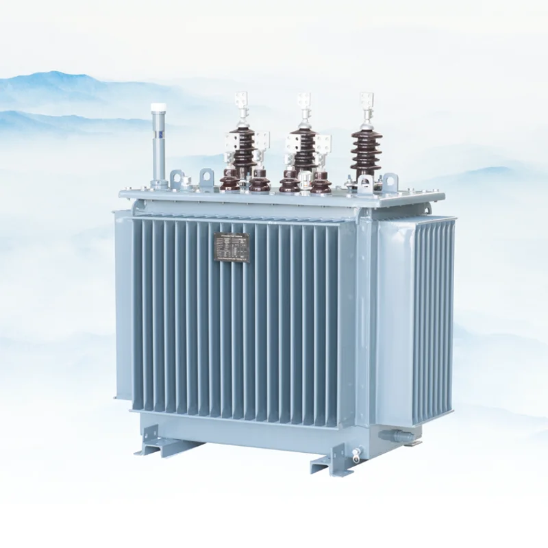
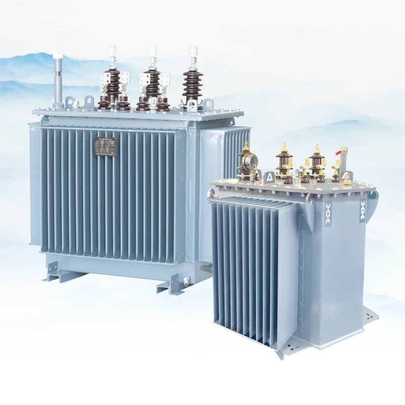
Description
Oil-Immersed Distribution Transformer at a Glance
An oil-immersed distribution transformer steps a medium voltage feeder down to the utilisation voltage, usually 0.4 kV, using insulating oil for both insulation and cooling. The oil carries heat out of the winding and core to the tank surface, which is why this type holds up under continuous load and tolerates overload better than a dry-type unit of the same rating.
The range covers 25 kVA to 2,500 kVA at 10 kV, 11 kV, 20 kV, 30 kV and 33 kV, with a 30 kV build available where a project specifies that class directly rather than through a standard IEC level. Every unit is configured against the network data rather than chosen from a stock list: capacity, voltage combination, tap range, vector group, losses and tank finish are fixed at order.
Where the project instead specifies a 35 kV feeder, the class changes and the build is quoted separately: see the 35 kV oil-immersed distribution transformer page.
Where 30 kV Sits Among Standard Classes
For a 30kV oil-immersed distribution transformer, the IEC hierarchy runs through 24 kV, 36 kV and 40.5 kV as the highest voltage for equipment. A 30 kV nominal system usually sits inside that 36 kV class, but the owner’s specification may call for 30 kV rated equipment directly, particularly where an existing network is being extended rather than built new.
Two consequences follow for a buyer:
- The insulation level is not implied by the name. A 30 kV unit may be built to 36 kV insulation or to a project-specific level. State both the nominal system voltage and the required withstand figures.
- The tap range has to be explicit. On a non-standard class the tapping is set to suit the actual supply variation at site, not to a catalogue default.
If the project is on a new-build 33 kV network, confirm the target class with the utility before ordering. Equipment built to 30 kV rating may not satisfy a specification written around 36 kV.
What a Unit Is Configured From
| Input | What it decides | Default if unspecified |
|---|---|---|
| Capacity in kVA | Core and winding size | Not assumed — required |
| Primary and secondary voltage | Turns ratio | Not assumed — required |
| Tap range | Voltage adjustment at site | ±5% off-circuit |
| Vector group | Phase displacement | Dyn11 |
| Impedance | Fault current at the terminals | Standard for the capacity |
| Winding material | Loss and price | Copper |
| Cooling | Usable capacity | ONAN |
| Accessories | Protection and monitoring | Temperature control, pressure relief |
The defaults in the right-hand column are what we assume when an inquiry leaves a field blank. They are stated here so that a quotation can be read against them: if a default does not match your scheme, it needs to be corrected before the order rather than discovered at drawing approval.
Capacity and Loss Selection
Capacity for a 30kV oil-immersed distribution transformer follows the coincident load plus the margin your standard requires, and the largest motor usually decides it rather than the steady-state total. A transformer sized exactly to the connected load will be overloaded the first time the largest motor starts.
Losses are the second decision and the one that gets skipped. Where the specification caps no-load and load loss, the cap determines the core grade and the winding section, which is why two quotations for the same capacity can differ substantially in price. Where no cap is stated, the standard design applies and the test report gives the actual values.
For the same voltage class built at 35 kV, the 35kV oil-immersed distribution transformer page lists a full capacity table from 50 to 2,500 kVA that shows how loss scales with rating.
Ask for both figures at quotation: the no-load loss in watts and the load loss at 75 °C in watts. A quotation that gives only a percentage efficiency figure cannot be compared with one that gives watts, because efficiency depends on the load point you assume.
Tap Range and Vector Group
Taps are off-circuit: the unit is de-energised before the tap is changed. The standard range is ±5 percent in 2.5 percent steps, with ±2 × 2.5 percent available where finer adjustment is needed.
Vector group decides the phase displacement between primary and secondary, and it has to match the rest of the network or the transformer cannot be paralleled with an existing unit. Dyn11 is the common default for a distribution transformer; if the site already has units in service, match their vector group rather than the default.
Oil-Immersed or Dry-Type at This Class
At 30 kV the choice between oil and dry follows the installation location rather than the technology.
- Oil-immersed for outdoor installation in a fenced compound, a pad or a pole-mounted arrangement, and for any duty where overload capability matters.
- Dry-type for indoor installation inside an occupied building, where a fire load of insulating oil would require a fire-rated enclosure or a containment pit. Our medium voltage dry type transformer series covers that side.
The cost difference is real: an oil unit of the same capacity is cheaper per kVA. The decision should not be made on price alone where the unit sits inside a building, because the enclosure and fire-protection cost of the oil alternative falls outside the transformer quotation.
Where a Distribution Transformer Fits
Distribution transformer and power transformer are not marketing terms. They describe where the unit sits in the network, and that position decides what it has to survive.
A distribution transformer sits at the end of the chain, between the medium voltage feeder and the utilisation voltage, close to the load. It is built in volume, sized from 25 kVA to 2,500 kVA, and judged on losses, impedance and how well it tolerates an unbalanced load. A power transformer sits upstream at the substation, transforms between transmission and sub-transmission levels, and is judged on through-fault strength, cooling class and on-load tap changer behaviour. The transformer range covers both, but they are not interchangeable and a quotation for one will not serve as a quotation for the other.
Two related phrases appear in enquiries and mean the same thing here. “Power distribution transformer” is a distribution transformer applied at a substation or a large industrial board. “Transformer and distribution” describes a package, the transformer plus its switchgear and protection, which is quoted as a substation solution rather than as a single unit.
Step-Down Duty and What Drives the Price
A distribution transformer is almost always a step-down transformer: the primary takes the feeder voltage and the secondary delivers 400 V or 415 V to the board. The ratio is set by the network rather than chosen, so what the buyer actually controls is capacity, impedance and loss class.
Three things move the price of a step-down distribution transformer, in this order. Winding material first: copper costs more than aluminium at the same rating and runs cooler at the same losses. Loss class second: a low-loss build uses more core steel of a better grade, costs more up front and less over twenty years. Tank and finish third: a standard painted tank and a hot-dip galvanised tank with a high creepage bushing set are different products at the same kVA.
That is why a “cheap power transformer” quotation and a properly specified one are rarely comparable. The cheapest units on an open market are usually aluminium wound, built at the lowest loss class the tender allows, with a standard tank. That is a legitimate product for a temporary site and a poor one for a feeder that will run thirty years. Ask for the loss figures and the winding material in writing before comparing prices, and the comparison becomes possible at all.
Capacity, Voltage and the Standard Configurations
The common builds are easier to list than to describe. Capacity runs 25, 50, 100, 160, 200, 250, 315, 400, 500, 630, 800, 1,000, 1,250, 1,600, 2,000 and 2,500 kVA. A 500 kVA unit is the single most frequently ordered rating on a 10 kV or 11 kV feeder, and 1,000 kVA is the usual choice where one feeder serves an industrial estate.
Voltage combinations follow the network: 10/0.4 kV, 11/0.433 kV, 20/0.4 kV, 22/0.4 kV, 30/0.4 kV and 33/0.4 kV are all standard builds. Three phase is the default above roughly 100 kVA. Single phase units exist for rural distribution and small loads, and they are quoted as their own build rather than as a variant of a three phase unit.
Vector group, impedance and tap range are the three settings that most often arrive wrong in an enquiry. Dyn11 is the default for distribution duty; impedance is set against the downstream fault level rather than copied from the last project; and the tap range has to match the real feeder voltage variation. Send the network data and the three fall out of it.
Outdoor Installation
Standard build is outdoor, on a concrete plinth, with the cable box and the conservator accessible for maintenance. Clearances to walls, to other equipment and to the boundary follow the local code for the voltage class and for the oil volume.
For the 30kV oil-immersed distribution transformer, two items belong in the inquiry rather than in the installation drawing: the pollution level at site, which sets the creepage of the bushings, and the seismic or wind loading if the site is in an exposed area. Neither can be added to a finished unit.
Standards and Tests
Units are built and tested to the oil-immersed transformer standards applicable to the project, normally IEC 60076 or GB 1094. Routine tests on every unit cover winding resistance, ratio and polarity, no-load loss and current, load loss and impedance, applied voltage withstand and induced voltage withstand, and oil dielectric strength.
Type test reports covering temperature rise and lightning impulse are available for project documentation. Factory acceptance testing can be witnessed at our works where the project requires it.
Manufacturer Supply, OEM and Wholesale
The 30kV oil-immersed distribution transformer range is manufactured and supplied direct. Project buyers receive drawings, loss figures and test reports for consultant approval before production; EPC contractors order against a frozen specification; distributors hold a standing specification for repeat supply.
Because 30 kV is a project-specific class rather than a catalogue frame, the unit is built to your network data in the first place, and non-standard tapping and vector group are normal rather than exceptional.
Price, MOQ and Lead Time
- MOQ. One unit. Standard capacities carry no minimum quantity.
- Price drivers. Capacity, winding material, loss cap, impedance, tap range, accessories and quantity.
- Lead time. Confirmed against the production schedule. Non-standard voltage classes take longer than standard ratings because the winding is a one-off.
- Payment. Deposit with balance against the bill of lading copy; letter of credit for project quantities.
What to Send With Your Inquiry
- Nominal system voltage, and the required insulation level
- Capacity in kVA
- Primary and secondary voltage, and the tap range
- Vector group and impedance
- Loss values your specification caps, if any
- Winding material: copper or aluminium
- Indoor or outdoor installation, pollution level and altitude
- Accessories required
- Quantity, destination port and required delivery date
Send those through the quote form on this page. On a non-standard voltage class the insulation level and the tap range are the two items that most often need a second round, so including both shortens the quotation.
FAQ
Is 30 kV a standard IEC class?
What insulation level should I specify?
Copper or aluminium windings?
What if I leave a field blank?
Can losses be capped?
What is the MOQ?
Request Quote
Tell us your specifications, quantity, or application scenario and we will reply with a tailored quote.