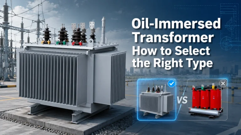
A power transformer takes electrical energy at one voltage and transfers it to another circuit at a different voltage, using a magnetic field instead of a direct electrical connection. It steps voltage up for efficient long-distance transmission or steps it down for safe use in factories, buildings, and homes. The device does not generate power. It changes the voltage level while keeping frequency the same and transferring nearly all the input power to the output.
The Physics That Makes It Work
Every power transformer relies on one discovery: Faraday’s law of electromagnetic induction. The rule is simple to describe but powerful in practice. When a changing magnetic field passes through a coil of wire, it produces a voltage across that coil. Move a magnet near a wire, and current flows. In a transformer, the changing magnetic field comes not from a moving magnet but from alternating current flowing through the first coil.
Here is why alternating current (AC) matters. Direct current (DC) creates a steady magnetic field that does not induce voltage in a nearby coil after the initial moment of connection. AC, on the other hand, reverses direction 50 or 60 times per second. Each reversal changes the magnetic field, and each change induces voltage in the secondary winding. This continuous induction is what makes transformers work reliably for decades.
Two physical facts summarize the underlying principle:
A conductor carrying AC produces a changing magnetic field around it.
A conductor placed inside a changing magnetic field has voltage induced across it.
Put a coil with AC on one side of a magnetic core, and a second coil on the other side, and you have a transformer. For a broader look at the design concepts behind these devices, see our guide on transformer core technology.
Inside a Power Transformer – The Main Parts
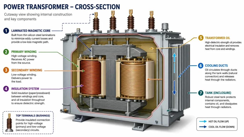
Knowing the parts makes the working principle easier to follow. Below are the elements every power transformer relies on.
Part
What It Does
Primary winding
Coil connected to the power source. Current entering here creates the magnetic field.
Secondary winding
Coil where voltage is induced. Connected to the load that needs power.
Magnetic core
Laminated steel structure that channels the magnetic flux from the primary to the secondary winding with minimal loss.
Laminations
Thin insulated steel sheets that make up the core. Each layer blocks circulating eddy currents, reducing wasted energy.
Insulation
Material separating windings from each other and from the core. Oil-impregnated paper, epoxy resin, or air, depending on the transformer type.
Cooling system
Removes the heat that comes from core and winding losses. Oil radiators or fans keep the temperature within safe limits.
Tap changer
Adjusts the number of active turns to fine-tune output voltage when input voltage drifts.
Step by Step – How Energy Moves Through the Transformer
Follow the energy from input to output, and the working process becomes clear.
Step 1 – Primary winding energizes. AC voltage is applied to the primary coil. Current begins to flow, and the alternating nature of AC means the current continuously rises, falls, reverses direction, and rises again.
Step 2 – Magnetic flux builds in the core. The current in the primary winding creates a magnetic field. The laminated steel core provides a low-resistance path for this field, concentrating the magnetic flux so it passes efficiently through the secondary winding. Without the core, the flux would spread out and much less would reach the secondary side.
Step 3 – Flux links to the secondary winding. The changing magnetic field created by the primary cuts through each turn of the secondary winding. According to Faraday’s law, this changing flux induces an electromotive force (EMF) – a voltage – across the secondary terminals.
Step 4 – Voltage transforms according to the turns ratio. The relationship is direct: the ratio of primary turns to secondary turns determines the ratio of input voltage to output voltage. If the primary has 500 turns and the secondary has 100 turns, the turns ratio is 5:1. Apply 11,000 volts to the primary, and approximately 2,200 volts appears on the secondary. The formula is:
Vprimary / Vsecondary ≈ Nprimary / Nsecondary
Step 5 – The load draws power from the secondary. When you connect equipment to the secondary side, current flows through the load. At the same moment, the primary side draws more current from the source to match the power demanded. The transformer does not store energy. It passes power through in real time.
Step 6 – Losses convert to heat. No transformer is perfectly efficient. A small portion of input power becomes heat inside the core and windings. The cooling system dissipates this heat, and a well-designed power transformer operates at 97% to over 99% efficiency, depending on its size and loading.
Step-Up vs. Step-Down – Two Ways the Same Device Works
Every transformer follows the same physical law, but the winding arrangement determines whether it raises or lowers voltage.
Characteristic
Step-Up Transformer
Step-Down Transformer
Turns ratio
Secondary turns > primary turns
Secondary turns < primary turns
Output voltage
Higher than input
Lower than input
Output current
Lower than input (power conserved)
Higher than input (power conserved)
Typical location
Generation stations
Substations, near end users
Example
11 kV generator output stepped up to 132 kV for transmission
132 kV transmission voltage stepped down to 11 kV for distribution
The same transformer can technically operate in either direction. What makes it step-up or step-down is simply which side you energize. However, practical designs are optimized for one direction, so reversing operation should only be done after confirming with the manufacturer.
Where the Losses Come From
Understanding losses helps you read efficiency data and compare transformer options with confidence.
Iron losses (core losses) are present whenever the transformer is energized, even with no load connected. They come from two sources:
Hysteresis loss: The core steel resists being magnetized and demagnetized 50 or 60 times per second. Each magnetic cycle consumes a tiny amount of energy, and the cumulative effect is steady heat.
Eddy current loss: The changing magnetic field induces small circulating currents within the core steel itself. Laminating the core into thin sheets, each electrically insulated from the next, restricts these currents to keep losses low.
Copper losses (winding losses) grow with the load. They equal I²R, where I is the current flowing through the winding and R is the winding resistance. At light load, copper losses are small. At full load, they can be significant. This is why transformer efficiency curves typically peak somewhere between 50% and 80% of rated load, and why a transformer sized too large for the actual load wastes energy through unnecessary iron losses.
Stray losses are the smaller, harder-to-model losses from leakage flux that escapes the core and induces currents in the tank walls, structural steel, and other metal parts. Good design minimizes these, but they cannot be eliminated entirely.
How Three-Phase Power Transformers Work
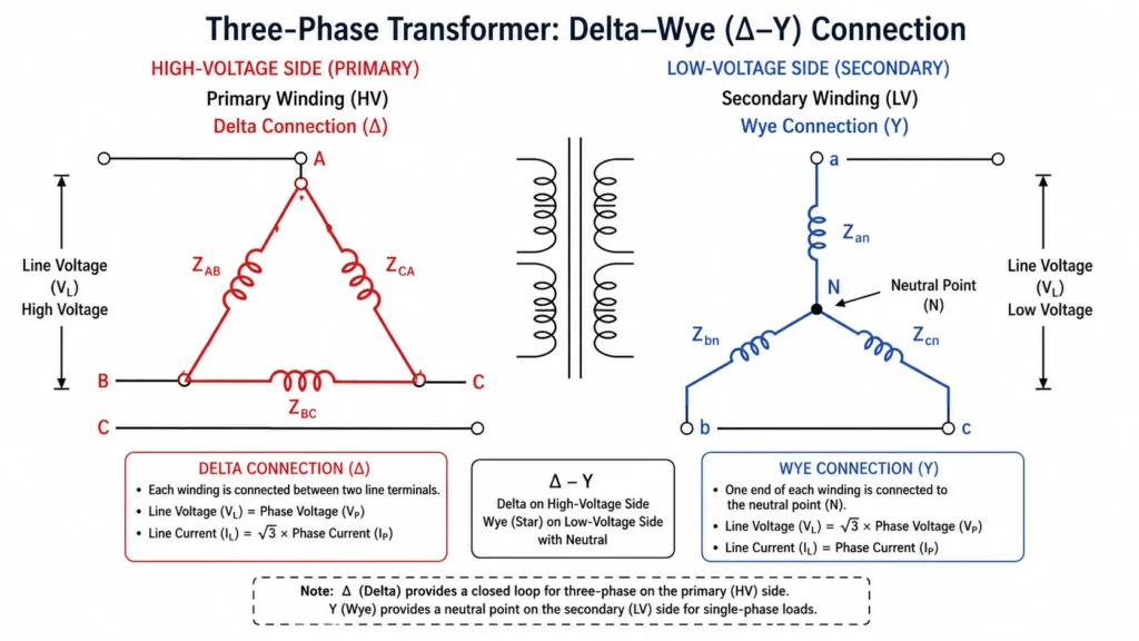
Most power transformers in generation, transmission, and industrial settings are three-phase units. Instead of having just one primary and one secondary winding, they have three sets of windings, one for each phase.
A three-phase transformer core typically has three limbs. Each limb carries the windings for one phase. The three AC phases are offset by 120 degrees from each other, so at any given instant the magnetic fluxes in the three limbs sum to zero at the common junction. This balanced design means the core can be more compact than three separate single-phase transformers would be.
The winding connections add another layer of design choice:
Delta connection: Windings are connected end-to-end in a closed triangle. No neutral point. Handles unbalanced loads well and can continue operating at reduced capacity if one phase fails.
Wye (star) connection: One end of each winding is connected to a common neutral point. Provides a neutral for grounding and gives two voltage levels: line-to-line and line-to-neutral.
Common combinations include delta-wye (Dy) for step-down substations and wye-delta (Yd) for step-up generation applications. Each vector group has specific phase shift and grounding characteristics that engineers match to the system requirements.
Choosing a Power Transformer That Works for Your System
Understanding how a power transformer works gives you the foundation for selecting the right one. But between the working principle and the purchase decision sit practical questions about kVA rating, voltage levels, cooling type, impedance, and environmental conditions.
If you are specifying a transformer for a new installation or replacing an existing unit, start by defining your input and output voltages, the total load in kVA, the cooling environment, and any special requirements such as harmonics, altitude, or seismic zone. From there, choose between dry-type and oil-immersed designs based on installation location and maintenance preference.
Kampa Electric manufactures power transformers for transmission, distribution, and industrial applications, with OEM and ODM customization available. Explore our product range or contact our engineering team to discuss your project requirements.
FAQ
Does a power transformer work with DC?
No. A power transformer requires alternating current. DC creates a constant magnetic field that does not continuously induce voltage in the secondary winding. Connecting DC to a transformer winding will cause high current and can damage the winding because the coil has very low resistance without the counter-EMF that AC operation provides.
Why does the core need to be laminated?
Lamination breaks the solid steel into thin insulated layers, which blocks the flow of eddy currents. Without lamination, the entire core would act as a single short-circuited turn, wasting energy as heat and reducing efficiency dramatically.
What determines the output voltage of a transformer?
The turns ratio between the primary and secondary windings sets the output voltage. Additional adjustment comes from the tap changer, which can add or remove active turns to correct for input voltage variation. Under load, the winding impedance also causes a small voltage drop, so the actual output voltage at full load is slightly lower than the no-load ratio would predict.
How efficient are power transformers?
Large power transformers operate at 99% to over 99.5% efficiency at full load. Smaller distribution units range from 97% to 99%. Efficiency depends on the quality of core steel, winding conductor selection, and how closely the actual load matches the design rating.
What happens when a transformer is overloaded?
Sustained overloading raises winding temperatures beyond design limits. This accelerates insulation aging and can eventually cause insulation breakdown and short circuits between turns or between windings and the core. Most transformers tolerate brief overloads because the thermal mass of the core, windings, and oil absorbs the extra heat, but continuous overloading shortens service life.
Why does a transformer hum?
The alternating magnetic field causes the core steel laminations to expand and contract slightly at twice the line frequency. This physical movement produces the familiar low hum. Loose core clamping, aging laminations, or DC offset in the supply can make the sound louder. A steady, moderate hum is normal and not a sign of trouble.
Every component serves a specific electrical, magnetic, or thermal function. Together they transfer thousands of kilovolt-amperes from one voltage level to another, silently and continuously, often for decades.
A power transformer is an electrical device that transfers electrical energy from one circuit to another through electromagnetic induction, changing voltage and current levels without changing frequency.