What Is a Power Transformer? A Complete Beginner Guide
Published: Author: Lisa
What Is a Power Transformer?
A power transformer is an electrical device that transfers electrical energy from one circuit to another through electromagnetic induction, changing voltage and current levels without changing frequency. In simple terms, it steps voltage up or down so that electricity can be transmitted efficiently over long distances and then safely delivered to homes, factories, and commercial buildings.
Power transformers are rated in kVA (kilovolt-amperes) or MVA (megavolt-amperes), which measures their apparent power capacity. They typically operate at higher voltage levels than distribution transformers and are found in generation stations, transmission substations, and large industrial facilities.
If you are researching power transformers for a project, knowing the basics helps you communicate with suppliers, read specifications, and choose equipment that fits your power system. This guide covers what a power transformer is, how it works, the main types, and what matters when you are selecting one.
How Does a Power Transformer Work?
Electromagnetic Induction – The Core Principle
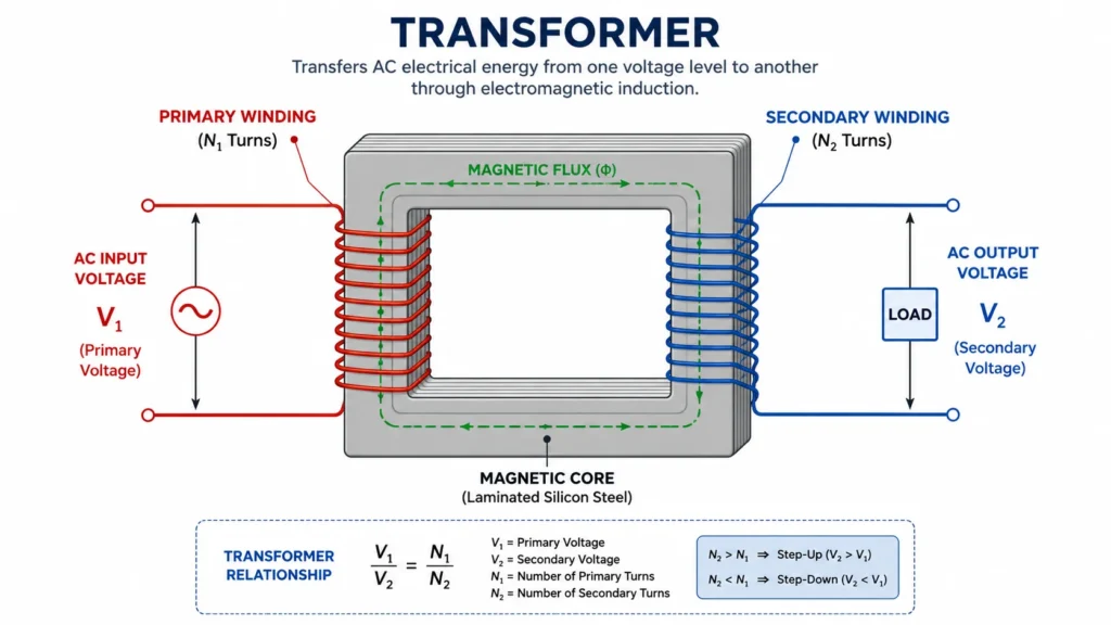
Every power transformer works on the same physical law: Faraday’s law of electromagnetic induction. When alternating current (AC) flows through a coil of wire, it creates a changing magnetic field around that coil. If you place a second coil nearby, within that magnetic field, a voltage is induced in the second coil.
The key point is that there is no direct electrical connection between the two coils. Energy transfers through the magnetic field. This is what provides electrical isolation between the input (primary) side and the output (secondary) side while still delivering power.
Turns Ratio and Voltage Change
The relationship between the number of wire turns on the primary and secondary coils determines whether a transformer steps voltage up or down:
Step-up transformer: The secondary coil has more turns than the primary. Output voltage is higher than input voltage. These are used at generation stations to raise voltage for long-distance transmission.
Step-down transformer: The secondary coil has fewer turns than the primary. Output voltage is lower than input voltage. These are used to reduce voltage for safe distribution and end use.
The voltage ratio is approximately equal to the turns ratio: Vprimary / Vsecondary = Nprimary / Nsecondary. A transformer with a 50:1 turns ratio, for example, can convert 11,000 volts on the primary side to 220 volts on the secondary side.
For a deeper look at what happens inside the core and windings, see our guide to how power transformers work.
Core Components of a Power Transformer
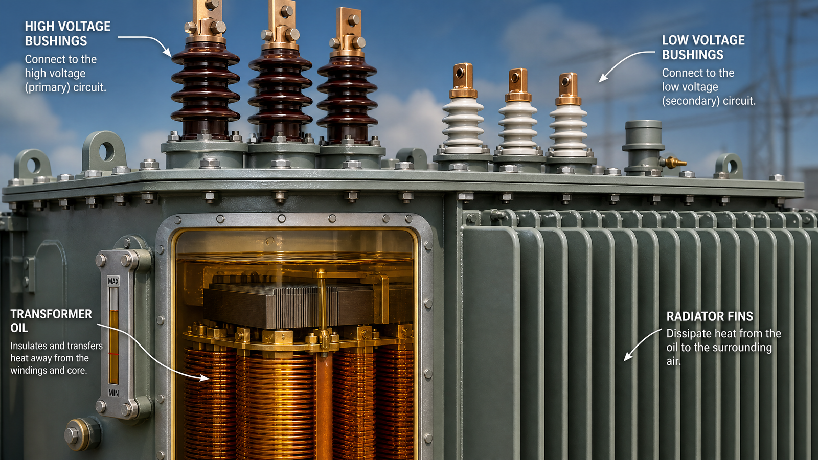
Although transformer designs vary by type and manufacturer, most power transformers share a common set of main components. The table below summarizes each part and its function.
Component
Function
Core
Built from laminated electrical steel sheets to guide magnetic flux between windings with minimal energy loss
Windings (Coils)
Copper or aluminum conductors wound around the core; the primary receives input, the secondary delivers output
Insulation system
Separates windings from each other and from the core; may be oil-impregnated paper, epoxy resin, or air, depending on type
Cooling system
Removes heat generated during operation; uses insulating oil with radiators (oil-immersed) or natural/forced air (dry-type)
Bushings
Insulated terminals that allow conductors to pass through the tank or enclosure wall without touching it electrically
Tap changer
Adjusts the effective number of winding turns to regulate output voltage when input voltage fluctuates
Tank / Enclosure
Houses the core and windings; sealed and oil-filled for outdoor units, ventilated for indoor dry-type units
Protection devices
Fuses, pressure relief devices, Buchholz relay (oil units), and temperature monitors that protect against faults and overloads
Types of Power Transformers
Step-Up vs. Step-Down Transformers
Every power transformer either raises or lowers voltage:
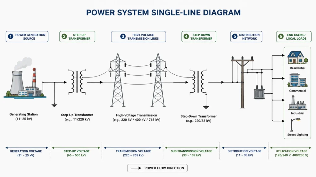
Step-up transformers are installed at power generation plants. They raise generator output voltage (typically 11-33 kV) to transmission levels (110 kV, 220 kV, 400 kV, or higher) so that power can travel hundreds of kilometers with minimal losses.
Step-down transformers are installed at substations. They reduce transmission-level voltage down to sub-transmission or distribution levels, eventually reaching voltages usable by industrial equipment, commercial buildings, and residences.
Step-up and step-down describe what a transformer does. The categories below describe what a transformer is – grouped by insulation and cooling method, and by where the unit sits in the network. Use the table to place a project in the right family before you go into detailed specifications.
Type
Cooling / insulation
Typical use
Oil-immersed transformer
Insulating oil
Outdoor substations, utilities, high-capacity distribution
High-voltage transmission and subtransmission substations
For most industrial, commercial, and utility distribution projects, the Oil Immersed Distribution Transformer is the dependable default. It uses insulating oil for both insulation and cooling, which gives it strong overload capacity, stable heat dissipation, and a long service life in outdoor installations.
Power Transformer vs. Distribution Transformer
People often use these terms interchangeably, but they refer to different equipment:
Feature
Power Transformer
Distribution Transformer
Voltage level
Transmission level (above 33 kV)
Distribution level (33 kV and below)
Rating
Typically above 5 MVA
Typically up to 5 MVA
Location
Generation stations and transmission substations
Distribution substations, pole-mounted, pad-mounted near end users
Load pattern
Designed for high efficiency at full load
Designed for efficiency across varying load levels
Operation
Usually operates at or near rated load continuously
Load fluctuates throughout the day
Common Applications of Power Transformers
Power transformers serve critical roles across the electrical grid:
Power generation plants – Step up generator voltage for efficient transmission over long distances.
Transmission substations – Step voltage between different transmission levels and connect regional grids.
Heavy industrial facilities – Supply high-power equipment such as arc furnaces, large motors, and electrolysis plants that require dedicated high-voltage feeds.
Railway traction systems – Provide the specific voltage and frequency needed for electric train networks.
Renewable energy integration – Connect solar farms and wind parks to the grid at appropriate voltage levels.
Mining operations – Deliver power to remote extraction sites where grid voltage must be stepped down for heavy machinery.
Key Specifications When Selecting a Power Transformer
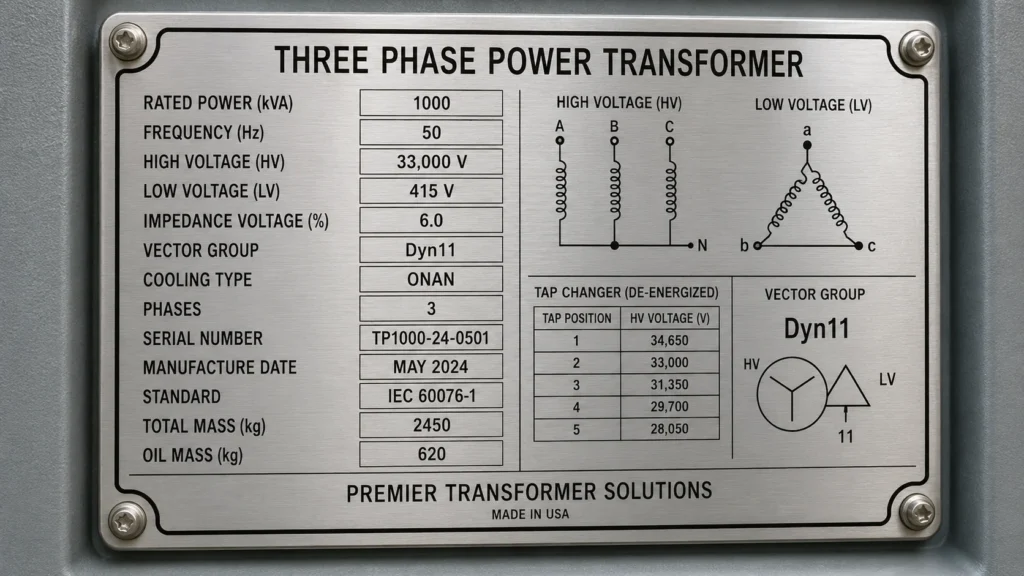
When you evaluate or specify a power transformer, these are the parameters that matter most:
kVA or MVA rating — The apparent power capacity. Select a rating that covers your maximum expected load plus a safety margin.
Primary and secondary voltage — The input and output voltage levels your system requires.
Frequency — Typically 50 Hz or 60 Hz depending on your region’s grid standard.
Number of phases — Single-phase or three-phase. Most industrial and utility applications use three-phase.
Cooling and insulation — Natural air, forced air, or oil circulation. Oil-immersed suits outdoor and high-capacity sites; dry-type suits indoor and fire-sensitive locations.
Impedance percentage — Affects short-circuit current levels and voltage regulation under load.
Winding configuration — Delta, wye, or zigzag arrangements with their associated vector groups (e.g., Dyn11, YNd5).
Temperature rise limits — Defines how hot the windings can get above ambient, which affects lifespan and overload capacity.
Insulation level — Basic Insulation Level (BIL) rated in kV, indicating the transformer’s ability to withstand voltage surges.
Efficiency and loss level — A low-loss design costs more up front but reduces operating cost every hour of a 25-40 year service life.
If you need help matching a transformer to your project, our power transformer guide walks through the selection process step by step.
FAQ
What is the difference between a power transformer and a distribution transformer?
Power transformers operate at transmission-level voltages (above 33 kV) and higher MVA ratings, typically running at or near full load in generation and transmission substations. Distribution transformers operate at 33 kV and below, with lower ratings, and are located closer to end users with fluctuating daily loads.
Why are transformers rated in kVA instead of kW?
Transformers are rated in kVA (apparent power) rather than kW (real power) because the manufacturer does not know the power factor of the load you will connect. The transformer handles both real and reactive power, and its losses depend on voltage and current, which kVA represents. You as the user must ensure the real power (kW) your equipment draws does not exceed the kVA rating adjusted by your power factor.
How long does a power transformer last?
A well-maintained power transformer typically lasts 25 to 40 years. Oil-immersed units can exceed 40 years with proper oil treatment, regular testing, and timely replacement of gaskets and bushings. Dry-type units generally have a 20-30 year service life. Operating conditions, loading patterns, and maintenance quality are the biggest determinants.
Can a power transformer be used in reverse?
Yes, most power transformers are electrically reversible. A step-down transformer can function as a step-up unit if you energize the secondary side. However, you must stay within the original voltage ratings, and the tap changer and protection settings may need adjustment. Always consult the manufacturer before reversing operation.
What causes a power transformer to fail?
The most common failure causes are insulation breakdown (from aging, overheating, or moisture ingress), winding deformation from short-circuit forces, tap changer malfunction, bushing failure, and cooling system faults. Regular testing, oil analysis, and thermal monitoring help detect early warning signs before failure occurs.
What is the difference between dry-type and oil-immersed power transformers?
Dry-type transformers use air for cooling and are typically installed indoors where fire safety is a priority. Oil-immersed transformers use insulating oil for cooling and are preferred for outdoor high-power applications because oil transfers heat more effectively, supporting higher ratings and better overload capacity.
Finding the Right Power Transformer for Your Project
Choosing a power transformer is not just about picking a kVA number from a catalog. Voltage levels, cooling method, insulation type, impedance, ambient conditions, and future load growth all shape the final specification. A mismatched transformer can cause voltage drop, excessive losses, premature aging, or safety risks.
Kampa Electric manufactures a wide range of power transformers, including dry-type and oil-immersed units, with full OEM and ODM customization. Our engineering team can help you define specifications, review your project requirements, and provide a transformer built to IEC and ISO standards.
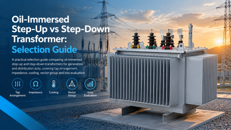
Step-up and step-down oil-immersed transformers differ in taps, impedance, cooling and loss weighting. Here is how to specify each duty for generation and distribution.
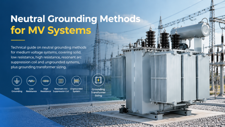
Compare solid, low resistance, high resistance, resonant and ungrounded MV neutrals, and size the grounding transformer and resistor that go with each method.
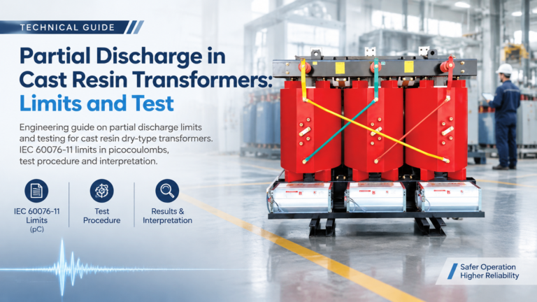
Why partial discharge decides cast resin transformer life: the 10 pC limit, how the IEC 60270 test runs, what the pC reading means, and the casting defects behind it.