What Is Inside a Power Transformer? Components Explained
Published: Author: Lisa
What You Will Find Inside Every Power Transformer
Open a power transformer and you do not see electronics or moving parts. You see steel, copper, insulation, and oil or air. Every component serves a specific electrical, magnetic, or thermal function. Together they transfer thousands of kilovolt-amperes from one voltage level to another, silently and continuously, often for decades.
This article walks through each internal component, what it looks like, what it does, and why it is built that way. Whether you are inspecting a unit, writing a specification, or learning how these machines are put together, starting from the inside makes everything else easier to understand.
Core – The Magnetic Highway
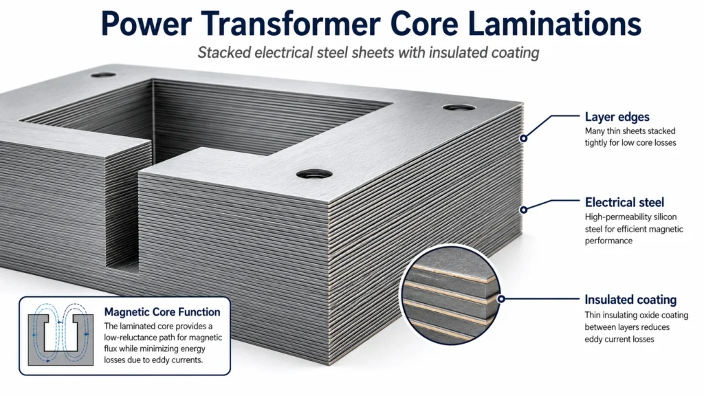
The core is the heaviest single component inside a power transformer. It is built from hundreds or thousands of thin steel sheets, each coated with insulation on one side, stacked and clamped together. This is not a solid block of iron, and that matters.
The core has one job: to carry magnetic flux from the primary winding to the secondary winding with the lowest possible resistance. Electrical steel is the material of choice because it magnetizes and demagnetizes easily, which keeps hysteresis losses small. The laminations, each typically 0.23 mm to 0.35 mm thick, are insulated from one another to block eddy currents. An eddy current is a small circulating current induced inside the steel itself by the changing magnetic field. Left unchecked, it would waste energy as heat. Lamination layers cut the path of these currents and force them to stay tiny.
The core shape varies by transformer size and type:
Core-type construction: The windings surround the core limbs. The most common design for power transformers. The core forms a rectangular frame with the windings wrapped around the vertical limbs.
Shell-type construction: The core surrounds the windings. Used in some larger units where extra mechanical bracing against short-circuit forces is needed.
For three-phase transformers, the core typically has three vertical limbs connected by top and bottom yokes. The magnetic flux from the three phases sums to near zero at the junction, so the return path can be smaller than it would be for three separate single-phase cores. Some large units use a five-limb design to reduce the overall height for transport.
The core is not electrically connected to the windings. It is grounded to the tank at a single point through a copper strap. If the core were left floating, static charge could build up and eventually arc to nearby metal. If it were grounded at two points, a circulating current could flow through the ground path and cause overheating.
Windings – Where Voltage Changes
The windings are coils of copper or aluminum conductor, carefully shaped and placed around the core. Every power transformer has at least two windings: the primary, which receives energy from the source, and the secondary, which delivers transformed voltage to the load. Some units add a third, called a tertiary winding, for auxiliary power, harmonic suppression, or system grounding.
Winding design is largely about managing voltage stress and short-circuit forces. The conductor is wrapped in layers of insulation. Between winding layers, pressboard cylinders and oil ducts provide additional dielectric strength and cooling channels. The physical arrangement of the primary and secondary windings on the core follows a consistent pattern.
Inside a typical power transformer, each winding on a core limb is arranged as concentric cylinders. Looking outward from the core steel, the order is:
Core limb
Inner insulation barrier
Low-voltage (LV) winding
Insulation gap with cooling oil duct
High-voltage (HV) winding
Outer insulation barrier
Placing the LV winding closest to the grounded core makes sense: the voltage stress between LV and ground is low, so less insulation is needed. The HV winding, carrying far higher voltage relative to ground, sits farther out where it is better separated from the core. This also makes it easier to bring the HV connections to the bushings.
The conductor itself is not a single thick wire. For larger ratings it is a continuously transposed conductor made of multiple thin, individually insulated strands that are woven so each strand spends equal time in every radial position. This equalizes current distribution and reduces eddy-current losses within the conductor itself. At lower ratings, rectangular or foil conductors are common in dry-type units.
Between each layer of the winding, pressboard spacers create radial oil ducts typically 3 mm to 8 mm wide. Oil circulates through these ducts to carry heat out of the winding and into the main cooling loop. The winding temperature is the critical limit on transformer loading: hot-spot temperature inside the winding determines insulation aging rate and remaining service life.
Insulation and Pressboard – The Invisible Lifeline
Insulation is everywhere inside a power transformer, and most of it is paper. Specifically, it is Kraft paper made from wood pulp, impregnated with mineral oil during the vacuum drying and oil-filling process. Paper wrap is applied directly to each conductor. Thicker pressboard sheets form barriers between windings, between windings and the core, and between phases.
The insulation system determines the transformer’s voltage class, its Basic Insulation Level (BIL), and ultimately its expected service life. Cellulose insulation ages with temperature. The widely used rule is that each 6 to 8-degree-Celsius increase in steady winding temperature cuts insulation life in half. This is why cooling and temperature monitoring matter so much.
During manufacturing, the assembled active part (core and windings together) goes through a vapor-phase drying process in a large oven. Moisture is driven out under vacuum and heat. Once dry, the unit is immediately filled with degassed insulating oil, which saturates the paper and prevents moisture from returning. A transformer with even 0.5% moisture content in its paper insulation has a significantly reduced dielectric margin compared to one dried to below 0.3%.
Insulating Oil – Coolant and Dielectric Combined
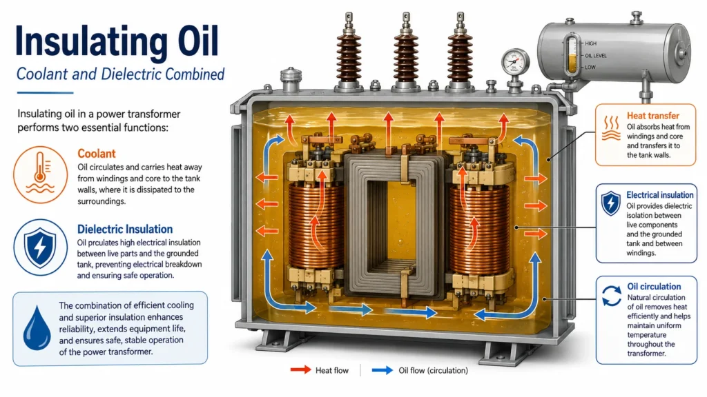
In oil-immersed power transformers, the tank is filled with mineral insulating oil that covers the entire core and winding assembly. The oil serves two essential purposes at once: it carries heat away from the windings and core to the tank walls and radiators, and it provides electrical insulation between energized parts at different potentials.
Good transformer oil has high dielectric strength, meaning it resists electrical breakdown under voltage stress. It also has low viscosity so it circulates freely through narrow winding ducts, and high flash and fire points for safety. Mineral oil is the standard, but synthetic esters and natural esters (vegetable-based oils) are increasingly used where environmental sensitivity or fire safety is a priority.
Inside an operating transformer, oil moves in a natural convection loop. Heated oil rises from the windings toward the top of the tank, flows into the radiators where it cools, and descends back to the bottom to be drawn up through the windings again. Larger transformers add pumps and fans for forced circulation when natural cooling is insufficient.
Oil also interacts chemically with the cellulose insulation. Over years of operation, it absorbs moisture and gases produced by paper aging and minor electrical discharges. This is useful: by sampling the oil and running dissolved gas analysis (DGA), engineers can detect arcing, overheating, and insulation degradation long before they cause a failure.
Tap Changer – Voltage Adjustment Under Load or Off-Load
The tap changer is a switch connected to taps on the winding. It changes the effective number of turns in small steps, typically plus or minus a total of 5% to 15% of the rated voltage, in steps of 1.25% or 2.5%. This allows operators to adjust the output voltage when the grid voltage is higher or lower than nominal.
There are two types:
Off-load tap changer: The transformer must be de-energized before switching. Simple, robust, and commonly used on distribution transformers where voltage is stable and seasonal adjustment is enough.
On-load tap changer (OLTC): Switches while the transformer carries full load current and voltage. This is the standard for power transformers in transmission substations, where grid voltage fluctuates throughout the day. The OLTC uses a diverter resistor or reactor to bridge between taps momentarily so the current is never interrupted during the change.
The OLTC is a mechanical switching device housed in its own oil-filled compartment or cylinder, separate from the main tank oil. This separation prevents carbon particles and contact wear debris from contaminating the insulation oil around the windings. The diverter switch contacts arc slightly during each tap change, and over thousands of operations this produces carbon that would degrade the main insulation if not isolated.
Bushings – The High-Voltage Doorway
Getting high-voltage current through a grounded steel tank wall without it arcing to the tank requires a bushing. A bushing is a cylindrical insulator that surrounds the conductor and provides enough surface creepage distance for the voltage class. The conductor runs through the center, and alternating layers of conductive foil and insulation inside the bushing body grade the electric field so it transitions smoothly from the high-voltage conductor to the grounded flange at the tank.
Oil-immersed transformers use several bushing types. For lower voltages, solid porcelain or composite (silicone rubber over fiberglass) bushings are common. For transmission-level voltages, oil-impregnated paper condenser bushings provide the highest reliability. The bushing has its own oil level visible in a sight glass at the top, and its own expansion space to accommodate thermal changes. A failed bushing can cause a catastrophic transformer fire, so bushing condition monitoring through power factor and capacitance testing is a standard maintenance practice.
Internal Protection and Monitoring Devices
Several protective devices live inside or are mounted directly through the tank wall:
Buchholz relay: Mounted in the pipe connecting the main tank to the conservator (expansion tank). It detects gas bubbles from internal faults and sudden oil surges. Low-rate gas accumulation triggers an alarm, while a large surge trips the transformer offline. This is one of the most sensitive and reliable internal fault detectors available.
Pressure relief device: A spring-loaded valve on the tank lid that opens if internal pressure exceeds a safe threshold, venting gas and preventing tank rupture during a severe internal arc fault.
Winding temperature indicator: A sensor that models the hot-spot temperature inside the winding by combining the top-oil temperature with the heating effect of the load current. Drives cooling fan control and alarm/trip contacts.
Oil level indicator: A float-and-pointer gauge on the conservator that shows whether the oil volume is within the normal range for the current temperature.
Silica gel breather: Connected to the conservator vent, it dries the air that enters and leaves as oil expands and contracts. The silica gel changes color from blue to pink when saturated with moisture.
Dry-Type Transformer Construction – Key Differences Inside
Not every power transformer contains oil. Dry-type transformers replace oil with solid insulation and air cooling. The core and winding design remains similar, but the insulation system and enclosure change significantly.
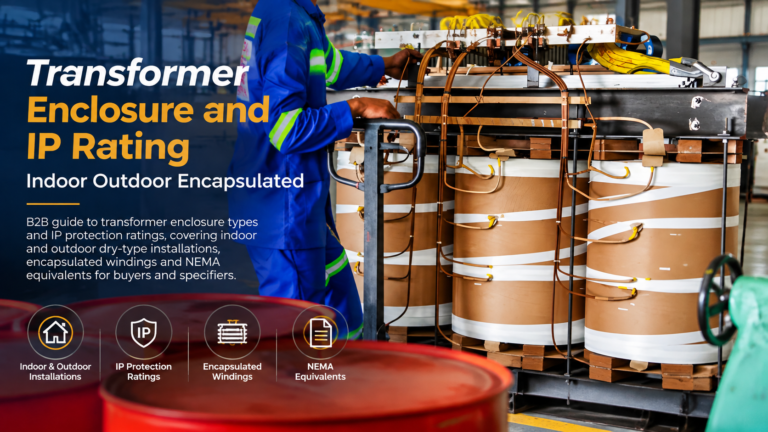
In a dry-type unit, the winding conductors are wrapped with Nomex, glass fiber, or other high-temperature materials. The entire winding may be vacuum-impregnated with varnish or encapsulated in epoxy resin. Cast-resin transformers take this further: the high-voltage winding is completely embedded in a solid epoxy casting with no air gaps, making it highly resistant to moisture, dust, and chemical contamination.
Cooling in a dry-type transformer is by natural convection of air through ventilated openings in the enclosure. Fans may be added for forced-air cooling. Without oil as a heat transfer medium, dry-type units operate at higher internal temperatures and are generally rated for lower MVA per unit than oil-immersed equivalents. But they eliminate oil containment, fire suppression, and oil testing from the maintenance routine, which can be a deciding advantage for indoor and urban installations.
Component Summary Table
Component
Material
Primary Function
Failure Consequence
Core
Cold-rolled grain-oriented silicon steel
Carries magnetic flux between windings
Increased losses, overheating, audible noise
Windings
Copper or aluminum, insulated with paper or enamel
Carries current; sets voltage ratio by turns count
Short circuit, insulation failure, arc fault
Insulation paper
Kraft cellulose paper
Dielectric barrier between conductors and to ground
Turn-to-turn fault, aging loss of life
Insulating oil
Mineral oil, synthetic ester, or natural ester
Cooling and dielectric insulation
Overheating, reduced dielectric strength, fire risk
Tap changer
Copper contacts, resistive or reactive diverter
Adjusts turns ratio to regulate output voltage
Loss of voltage regulation, arcing damage
Bushings
Porcelain, composite, or oil-impregnated paper
Insulates conductors passing through tank wall
Flashover, tank rupture, catastrophic fire
Pressboard barriers
Compressed cellulose pressboard
Inter-winding and phase-to-phase insulation
Dielectric breakdown during surges
Pressure relief device
Spring-loaded metal valve
Vents excess pressure to prevent tank rupture
Tank deformation or explosion if fails to open
FAQ
What is the heaviest part inside a power transformer?
The magnetic core is the heaviest single component. It consists of stacked laminated steel sheets and forms the structural center of the active part. In a 50 MVA power transformer, the core alone can weigh 20 to 40 metric tons.
Why is the core made of thin sheets instead of solid steel?
Thin laminated sheets, each insulated from the next, block the flow of eddy currents that would circulate in a solid core and waste energy as heat. Without lamination, core losses would be unacceptably high and the transformer would overheat rapidly.
Can you open a transformer to inspect the inside?
Yes, but only during planned maintenance or after draining the oil. Opening a sealed transformer exposes the insulation to moisture in the air. The exposure must be minimized, and the unit must go through a drying and re-impregnation process before returning to service. This is a specialized operation, not routine inspection.
How do you know if the insulation inside is degrading?
Dissolved gas analysis (DGA) of the oil detects carbon monoxide and carbon dioxide produced as cellulose paper ages. Furan compounds, also measured in oil, are direct chemical markers of paper degradation. Combined with winding temperature records and power factor testing, DGA gives a reliable picture of insulation condition without opening the tank.
What is the difference between windings in dry-type and oil-immersed transformers?
The conductor material and magnetic design are similar, but the insulation system differs. Oil-immersed windings use oil-impregnated paper that relies on the surrounding oil for cooling and dielectric strength. Dry-type windings use high-temperature materials such as Nomex or glass fiber and may be varnish-impregnated or cast in epoxy. Dry-type windings run hotter and do not benefit from the oil’s convective cooling.
What happens inside a transformer during a short circuit?
Short-circuit current can reach 10 to 20 times the rated current. This produces enormous electromagnetic forces between the windings that try to push them apart radially and compress them axially. The windings and their clamping structure must be designed to survive these forces without permanent deformation. A winding that shifts even a few millimeters under short-circuit stress loses its dielectric clearances and is at high risk of subsequent failure.
Understanding What Is Inside Leads to Better Decisions
Once you know the core, the windings, the insulation, and the protective devices, reading a specification or a test report becomes a lot less abstract. Every parameter on a nameplate connects to what is physically inside the tank or enclosure. The cooling class connects to oil ducts and radiator surfaces. The BIL rating connects to paper thickness and oil gap clearances. The impedance connects to the physical spacing between primary and secondary windings.
For a detailed explanation of how all these components work together during operation, read our guide on transformer working principles. If you are comparing transformer types for a project, see our dry-type vs oil-immersed comparison, which covers how these internal design choices translate into performance, safety, and maintenance differences in the field.
Kampa Electric manufactures power transformers with OEM and ODM customization. Contact our team to discuss your specifications.
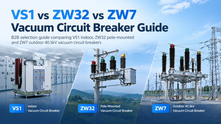
How to choose between VS1 indoor, ZW32 pole-mounted and ZW7 40.5 kV outdoor vacuum circuit breakers, including type codes and breaking capacity sizing.
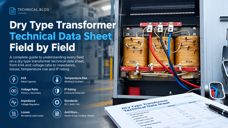
A field-by-field walkthrough of the dry type transformer technical data sheet, including the eight fields that move the price and the errors that cause disputes.