Transformer for EV Charging Stations & Charging Hubs
Published: Author: Lisa
Sizing a transformer for EV charging station starts with a calculation that catches people out: the number on the charger is not the number you size to. A 350 kW DC dispenser is rated by what it delivers to the vehicle, while the service, the transformer and the switchboard have to carry what it draws from the grid — which is larger, and in some jurisdictions treated more strictly than an ordinary load of the same size.
This guide covers the two rules that drive most of the calculation, how to pick a K-rating for chargers, how the site type changes the answer, and why an energy management system is often a bigger lever on transformer size than anything in the electrical design.
Why EV charging is a different kind of load
Four characteristics separate charging from a conventional commercial load.
The load is behind a rectifier. Everything from a 7 kW wallbox to a 350 kW dispenser converts AC to DC, and that conversion injects harmonic current back into the transformer.
Sessions are intermittent and clustered. A highway site sees bursts; a depot sees shift-change peaks. The average is unrepresentative and the peak is what the transformer has to survive.
Loads are treated as continuous. Under NEC Article 625, EV charging is a continuous load, so circuits and feeders are sized at 125% of the charger’s maximum current rather than on a diversity assumption.
It is a new load on an old service. Most sites are retrofits, so the transformer is often the item that decides whether the project needs a utility upgrade.
Size from AC input kVA, not DC output kW
A DC fast charger is a rectifier. Its nameplate describes the DC output to the vehicle, and the AC input is larger because conversion is not lossless and the power factor is not unity. At 95% efficiency and 0.99 power factor, a 350 kW dispenser draws about 372 kVA, or roughly 447 A at 480 V three-phase — close to 6% more than the DC figure suggests.
That gap compounds across a site. In a twelve-dispenser plaza built from four 150 kW and eight 350 kW units, the AC input load is around 3,615 kVA. Held to 80% continuous loading, that needs a 5,000 kVA transformer and two 3,000 A lineups at 480 V. Sizing from the 3,400 kW of DC rating would have understated the equipment by roughly a third.
A worked hub example
Element
Value
Where it comes from
Dispensers
4 × 150 kW + 8 × 350 kW
Site design
Combined DC output
3,400 kW
Sum of nameplate ratings
AC input load
About 3,615 kVA
Nameplate ÷ efficiency, adjusted for power factor
Transformer, no load management
5,000 kVA at 80% loading
Sized on the full connected load, since no demand factor applies
Transformer, with energy management capping the site at 1,800 kW
About 2,500 kVA
Sized on the maximum load the control system permits
That last row is the most commercially significant line in the table. Halving the transformer by limiting simultaneous demand is usually cheaper than the transformer itself, and it also reduces the demand charge exposure that a 15-minute billing interval creates.
Continuous load: what it does to the calculation
Treating EV charging as continuous load removes the escape hatch most designers reach for. Branch circuits and feeders are sized at 125% of the charger’s maximum current, and the calculated load is the full connected load rather than a diversified guess. Two consequences follow: conductor and switchgear sizes climb, and a single large dispenser can look disproportionate on paper.
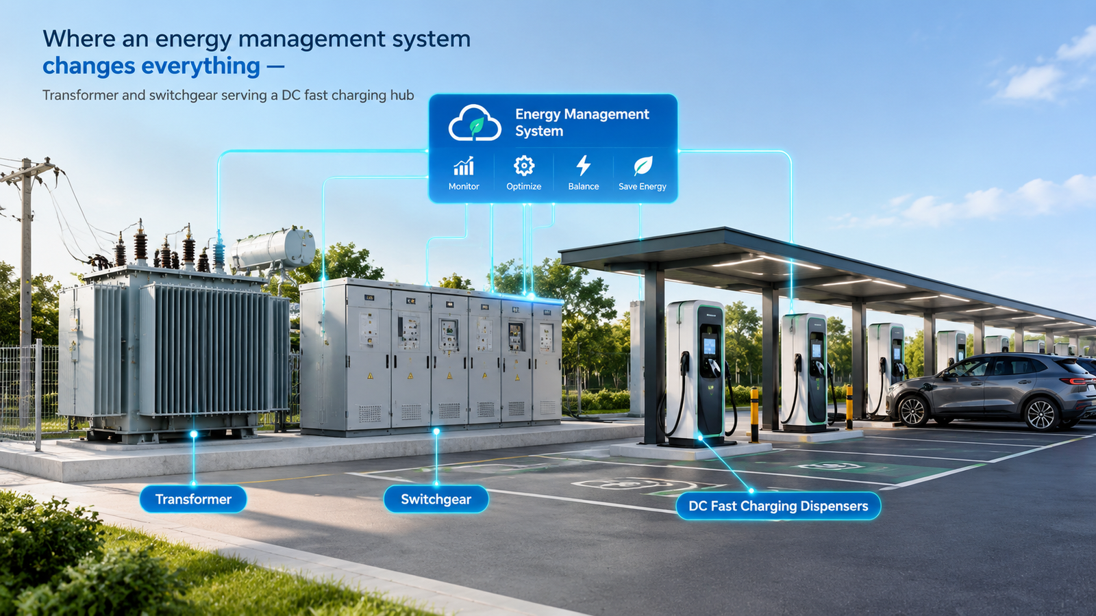
Where an energy management system changes everything
Where an energy management or automated load management system limits the maximum power the site can draw, the calculated load may be based on that limit instead of on the sum of the chargers. This is the standard route to a right-sized service, and it is worth commissioning the control system properly — the electrical design now depends on it functioning, so it is a protection-critical item rather than a convenience feature. Where no such system is installed, plan for the full connected load.
Harmonics and K-factor selection
Charger harmonics heat transformer windings faster than the RMS current suggests, because eddy-current losses rise roughly with the square of harmonic order. Total harmonic distortion from fast chargers can exceed 15%, well above the roughly 5% level at which a standard transformer begins to age faster than its design intended.
Back-to-back high-power sessions with a severe harmonic spectrum
Fleet depot with many parallel chargers
K-13, with harmonic mitigation where THD is high
Simultaneous operation across multiple rectifiers
Two clarifications that prevent over-specification. A K-rated transformer tolerates harmonic heating; it does not remove harmonics from the system. If the objective is to hold IEEE 519 limits at the point of common coupling, that is a separate decision — active filtering, or phase-shifting between two transformers supplying different charger groups. And a higher K-rating is not free: the units are larger, less efficient at light load, and usually lower in impedance, which raises available fault current downstream.
Diversity and demand factors by site type
Where a demand factor is permitted, it should reflect how the site is actually used rather than a round number. Charging behaviour varies enough between site types that a single assumption will be wrong somewhere.
Site type
Typical demand factor
Behaviour behind the number
Highway corridor, ultra-fast stalls
0.5–0.7
Brief, staggered stops; peaks depend on traffic patterns
Retail and shopping centre
0.6–0.8
Longer dwell times, moderate simultaneity
Fleet depot with scheduled shifts
0.7–0.9
Vehicles return together and charge on a common schedule — closest to simultaneous
Workplace or residential Level 2
0.5–0.6
Long parking durations, low coincidence
Then add a growth margin. Charging power per connector has risen steadily and megawatt-class charging is now appearing on highway corridors, so the honest assumption is that the site will need more capacity than it does today. The cheapest place to accommodate that is in the transformer size and in the busbar and conduit capacity provided at first build, not in a second civil project.
Dry type or pad-mounted: choosing by site
Site
Technology
Why
Indoor or underground parking structure
Cast resin dry type, IP23 enclosure
Fire codes restrict or prohibit liquid-filled equipment in enclosed parking; no oil leak or containment risk
Outdoor charging plaza, retail or highway
Pad-mounted liquid-immersed
Lower cost per kVA, weather-rated, tamper-resistant, suited to publicly accessible locations
Rooftop or space-constrained urban site
Dry type
Smaller clearance envelope and no bunding requirement
Large highway hub, 2,000 kVA and above
Liquid-immersed with forced-air cooling
Best cost and thermal performance at high ratings
The dividing line is location, not rating. Once the transformer is indoors in a space people use, the absence of an insulating liquid is worth more than the equipment saving on a pad-mounted unit. For dry-type installations, the enclosure rating, clearance and room sizing follow the same rules as any other indoor unit, and the dry type transformer sizes and dimensions chart covers the envelope and access planning.
Voltage selection and its effect on current
Most commercial charging sites take a medium-voltage service at 12.47 kV or 13.8 kV and step down to 480Y/277 V. Some jurisdictions permit a 600 V secondary, and at that voltage the same 3,615 kVA site draws about 3,479 A instead of 4,348 A — a 20% reduction in current, which shows up as smaller conductors, smaller switchgear and less copper. Where the local code allows it, that is a genuine capital saving, and the trade-off is that 600 V loads require different equipment ratings downstream.
The medium-voltage side is ordinary distribution practice, and our overview of medium and high-voltage power solutions describes how the incoming supply, transformer and protection are normally packaged for a site of this type. Impedance is worth stating rather than leaving to the supplier: around 5.75% is a common standard value, and lower impedance reduces voltage drop but raises available fault current on the charger side.
Efficiency at partial load
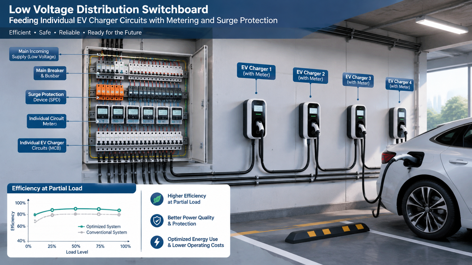
Charging is not a steady load, and the transformer spends most of its life well below nameplate. Level 2 installations in particular can spend the large majority of their operating hours somewhere between 15% and 40% loading, so the efficiency figure that matters is the one at part load, not at the rated point.
The arithmetic is worth doing before the purchase order. A single percentage point of efficiency loss on a megawatt-scale average load across several thousand operating hours a year is tens of thousands of kilowatt-hours — and if the transformer is indoors, that energy also has to be removed by the ventilation or air conditioning system, so it is paid for twice. Ask for the no-load and load loss figures, and evaluate them at the load your site will actually run at. The cost structure behind those figures is discussed in our power transformer price guide.
Protection, metering and surge protection
Overcurrent protection. Note that protection tables for transformers rated 1,000 V and below do not apply to a 13.8 kV unit, which falls under the higher-voltage rules. This is a common filing error on charging projects.
Surge protection. Install surge protective devices at the main switchgear and at each charger distribution panel, because the power electronics downstream are far less tolerant of transients than the equipment they replaced.
Metering. Revenue-grade metering for utility billing, plus sub-metering if the operator allocates cost by charger, tenant or vehicle.
Earth fault and insulation monitoring. Particularly where the chargers are in a location with public access and wet conditions.
Temperature monitoring. Winding sensors feeding the site control system, so that a prolonged hot spell or a blocked ventilation path shows up as data rather than as a failure.
Where the site also has battery storage to shave demand peaks, the transformer and the storage system are designed together — the storage changes the load profile the transformer sees, and the interaction with protection is the part that catches projects out. That coordination sits alongside the wider distribution protection design described in our industrial power distribution and protection overview.
Designing for the next charger generation
Provide busbar, conduit and switchboard capacity for the next step up in charger power, even if the transformer is right-sized today.
Reserve physical space for a second transformer and its clearance envelope.
Specify the K-rating for the harmonic content you expect, not the content you measure on day one.
Confirm the site’s maximum demand against the utility’s available capacity before finalising the charger count.
Decide whether energy storage will be added later, because it changes the load profile the transformer is designed around.
Specification checklist
State the AC input load in kVA, derived from charger nameplate divided by efficiency and adjusted for power factor.
State whether an energy management system limits site demand, and if so, the limit it enforces.
Confirm the continuous-load treatment and the resulting 125% sizing for circuits and feeders.
Specify the K-factor rating from the expected harmonic spectrum and charger mix.
State the primary and secondary voltages, and confirm whether a 600 V secondary is permitted locally.
State the impedance and confirm the available fault current is acceptable downstream.
Require declared no-load and load losses, and evaluate them at the site’s real average loading.
State the enclosure, IP rating, design ambient and whether the location is indoor or outdoor.
Confirm the physical envelope, clearance and access route against the site plan.
Include surge protection, metering and temperature monitoring in the scope.
Conclusion
EV charging projects are decided by two numbers: the AC input kVA, which is larger than the DC nameplate suggests, and the demand the site is allowed to draw, which an energy management system can cut dramatically. Get those right, apply the continuous-load treatment honestly, and choose the K-rating from the charger mix rather than a default. Then match the technology to the site — cast resin indoors, pad-mounted outdoors — and price the losses at part load, because that is where the transformer will spend its operating life. For chargers in buildings and covered structures, the cast resin data in our SCB series dry type transformer range is a practical starting point, and the thermal classes behind the specification are set out in our guide to transformer insulation class and temperature rise.
FAQ
How do I size a transformer for an EV charging station?
Start from the AC input kVA of each charger rather than its DC output rating, sum the site load, apply a demand factor appropriate to the site type where one is permitted, then confirm the continuous-load treatment and add a growth margin. Where an energy management system caps site demand, the transformer can be sized on that cap instead of the full connected load.
What K-factor does an EV charger transformer need?
K-4 for Level 2 dominated sites with mixed building load, K-9 for mixed Level 2 and moderate DC fast charging, and K-13 for dense DC fast charging hubs and fleet depots. The rating should follow the expected harmonic spectrum, and it does not by itself reduce harmonics on the system.
Should an EV charging transformer be dry type or oil-filled?
Cast resin dry type for indoor and underground parking structures, where fire codes restrict liquid-filled equipment. Pad-mounted liquid-immersed for outdoor charging plazas and highway hubs, where cost per kVA and weather resistance are the deciding factors.
Why is the transformer larger than the sum of the charger ratings?
Because a charger’s nameplate describes its DC output to the vehicle, while the transformer carries the AC input, which is roughly 6% higher after conversion losses and power factor. On top of that, EV charging is treated as a continuous load, which affects how the load is calculated and how circuits are sized.
What is a DC fast charging transformer?
It is a distribution transformer dedicated to supplying one or more DC fast chargers, typically stepping a 12.47 kV or 13.8 kV service down to 480Y/277 V, and specified with a harmonic rating suited to the rectifier load behind it.
How does an energy management system reduce transformer size?
By limiting the maximum power the site can draw at any moment, which lowers the calculated load the transformer has to be sized for. On a large hub this can halve the required rating, so the control system becomes a load-bearing part of the electrical design.
What demand factor applies to EV charging?
It depends on the jurisdiction and on whether load management is installed. Where a demand factor is permitted, highway ultra-fast sites commonly use 0.5–0.7, retail sites 0.6–0.8, and fleet depots 0.7–0.9 because vehicles return and charge together.
Do charging hubs need harmonic filtering?
Only where harmonic distortion at the point of common coupling would exceed applicable limits. A K-rated transformer protects itself from harmonic heating; harmonic mitigation — active filters or phase-shifting between charger groups — is a separate measure used to protect the supply.
How to specify a dry type transformer for mining: flameproof Group I protection, overload for direct-on-line motor starting, dust design and mobile substations.
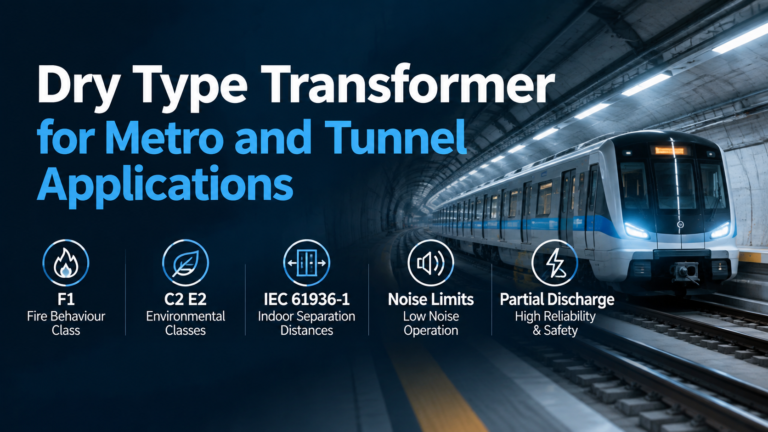
How to specify a dry type transformer for metro and tunnel duty: F1 fire behaviour, C2 E2 environmental classes, IEC 61936-1 separation and partial discharge limits.
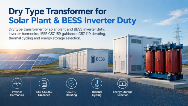
How to specify a dry type transformer for solar plant and BESS duty: IEEE C57.159 guidance, inverter harmonic losses, derating, thermal cycling and energy storage selection.