Dry Type Transformer Sizes & Clearance Chart (30-2500 kVA)
Published: Author: Lisa
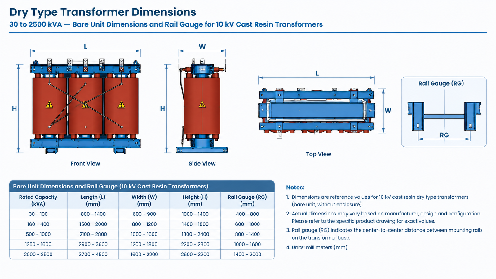
If you are laying out an electrical room, the first question is rarely “which transformer” and almost always “will it fit”. Dry type transformer sizes are reasonably predictable: for the common 10 kV / 0.4 kV cast resin family, a 30 kVA unit occupies roughly 900 × 600 mm at floor level, a 1000 kVA unit roughly 1680 × 1030 mm, and a 2500 kVA unit roughly 2150 × 1250 mm — before any enclosure is fitted. Around those footprints you then need working clearance, ventilation height, a route to get the unit in, and a floor that will carry it.
This guide gives you the dimension chart from 30 to 2500 kVA, the clearance rules from both the IEC/GB tradition and the NEC tradition, and a room-sizing formula you can apply to a real project in a couple of minutes.
Dry type transformer sizes at a glance
Three numbers decide whether a room works: the footprint (length × width), the height, and the weight. Weight matters as much as footprint, because it drives both the floor slab and the rigging plan — a 2500 kVA dry-type unit weighs around 5.2 tonnes, and it has to arrive through a doorway before it can sit on its plinth.
Two cautions apply to every chart you will find, including the one below. First, published dimensions usually describe the bare unit without an enclosure; adding an IP20 or IP23 metal enclosure typically increases each horizontal dimension by 100–300 mm and raises the top clearance requirement. Second, manufacturers build to slightly different core and winding designs, so a 10–20% spread between catalogues is normal. Treat the chart as a planning tool and the manufacturer’s outline drawing as the authority.
Standard kVA ratings you can actually buy
Dry-type transformers are built in preferred steps rather than continuously. In the 10 kV class the usual ladder runs 30, 50, 80, 100, 125, 160, 200, 250, 315, 400, 500, 630, 800, 1000, 1250, 1600, 2000 and 2500 kVA. If your load calculation lands between two steps, the decision is usually between the next standard size up and a custom rating — and standard is almost always cheaper and faster, even when it means a little unused capacity.
Dry type transformer dimensions: 30 to 2500 kVA
The chart below shows typical bare-unit dimensions and weights for 10 kV / 0.4 kV cast resin dry-type transformers, with the rail gauge needed for the foundation channels. Where a cell shows a range in practice, the values here reflect common mainstream designs.
Rating
Length × width × height (mm)
Total mass (kg)
Rail gauge (mm)
30 kVA
900 × 600 × 950
380
550 × 550
50 kVA
950 × 650 × 1000
480
550 × 550
80 kVA
1000 × 680 × 1050
580
660 × 660
100 kVA
1050 × 700 × 1100
650
660 × 660
125 kVA
1100 × 720 × 1150
750
660 × 660
160 kVA
1150 × 750 × 1200
850
820 × 820
200 kVA
1200 × 780 × 1250
950
820 × 820
250 kVA
1250 × 800 × 1300
1100
820 × 820
315 kVA
1300 × 830 × 1350
1250
820 × 820
400 kVA
1350 × 860 × 1400
1400
820 × 820
500 kVA
1430 × 900 × 1450
1600
820 × 820
630 kVA
1500 × 940 × 1500
1900
820 × 820
800 kVA
1580 × 980 × 1550
2200
820 × 820
1000 kVA
1680 × 1030 × 1600
2600
1000 × 1000
1250 kVA
1780 × 1080 × 1680
3100
1000 × 1000
1600 kVA
1880 × 1130 × 1750
3700
1000 × 1000
2000 kVA
2000 × 1180 × 1850
4400
1000 × 1000
2500 kVA
2150 × 1250 × 1950
5200
1000 × 1000
What changes the dimensions beyond kVA
Enclosure and IP rating. Moving from an open unit to IP20, IP23 or IP54 adds panels and often a larger base frame.
Temperature rise class. A design guaranteed at a lower temperature rise needs more conductor and core material, and is physically larger than a standard-rise unit of the same kVA.
Cooling fans. Forced-air cooling adds fan boxes and increases height and depth slightly.
Voltage class. A 20 kV or 35 kV primary needs longer creepage distances, which increases both height and length.
Winding material. Aluminium windings need a larger core and a larger frame than copper for the same rating.
Accessories. Temperature controllers, surge arresters and a neutral busbar all consume cabinet space.
Clearance requirements: two traditions, side by side
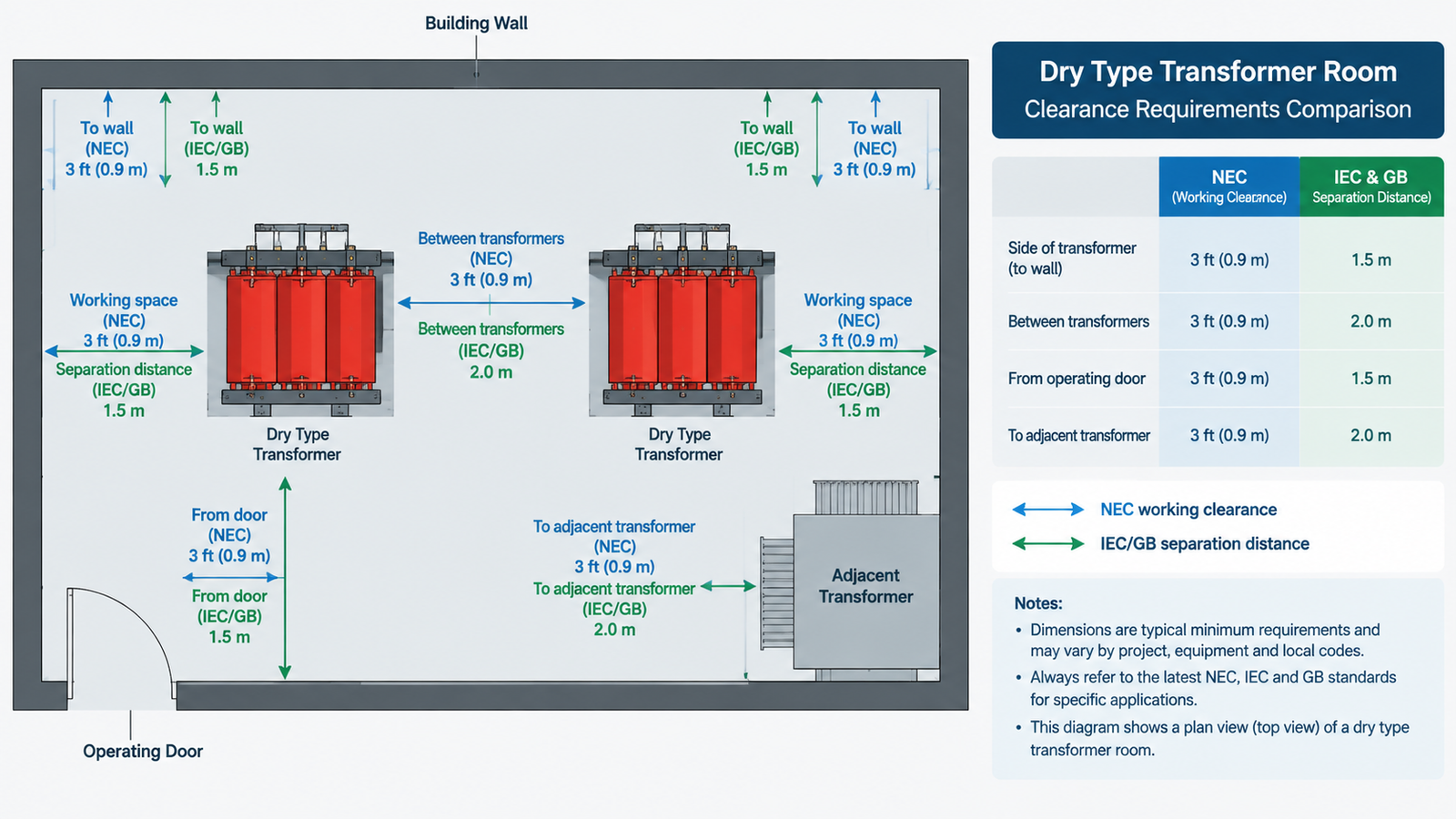
Clearance rules come from two different families of standard, and international projects often have to satisfy both. The IEC/GB tradition comes from installation codes such as GB 51348 and expresses distances from the enclosure or bare unit to walls and doors. The North American tradition comes from NEC Article 450 and separates working clearance from separation from combustible material.
Requirement
IEC / GB practice
NEC practice
Side and rear wall clearance, up to 1000 kVA
≥ 0.6 m (600 mm)
Working clearance 36 in (914 mm) at the operating face
Side and rear wall clearance, 1250–2500 kVA
≥ 0.8 m (800 mm)
Per manufacturer or authority having jurisdiction
Clearance to the door / operating face
≥ 0.8 m up to 1000 kVA; ≥ 1.0–1.2 m above
36 in (914 mm)
Separation from combustible material
Handled through enclosure IP rating
6 in (152 mm) up to 112.5 kVA; 12 in (305 mm) 113–1000 kVA; 18 in (457 mm) 1001–2000 kVA
Unit-to-unit spacing, same room
≥ 0.8 m between enclosures
36 in (914 mm) up to 112.5 kVA; 48 in (1219 mm) 113–1000 kVA
Top clearance for ventilation
≥ 600 mm to slab, tray or pipework
12 in (305 mm) minimum
Bare unit versus enclosed
Open units need a 1.8 m guard fence with ≥ 0.6 m to the unit
Guarding per local code
Numbers in a table are a starting point, not a design. Where a local authority imposes stricter distances, or where the room also contains switchgear, the binding figure is the largest one that applies. If your layout has to be signed off by a consultant, our dry type transformer specification guide sets out the associated environmental, climatic and fire classes that usually accompany the clearance drawing.
How to calculate transformer room size
Use the unit’s footprint plus the applicable clearances. The relationships are simple.
Room width = unit length + (2 × side clearance)
Room depth = unit width + rear clearance + front clearance
Room height = unit height + top ventilation space
Worked example: 1000 kVA in a commercial building
Bare unit 1680 × 1030 × 1600 mm, mass 2600 kg. Apply 600 mm to the rear and sides and 800 mm at the operating face, with 600 mm above for ventilation.
Room width = 1680 + 600 + 600 = 2880 mm
Room depth = 1030 + 600 + 800 = 2430 mm
Clear height = 1600 + 600 = 2200 mm
Floor area ≈ 2.88 × 2.43 = 7.0 m²
Worked example: 2500 kVA in an industrial substation
Bare unit 2150 × 1250 × 1950 mm, mass 5200 kg. Apply 800 mm to the rear and sides and 1200 mm at the door, with 600 mm above.
Room width = 2150 + 800 + 800 = 3750 mm
Room depth = 1250 + 800 + 1200 = 3250 mm
Clear height = 1950 + 600 = 2550 mm
Floor area ≈ 3.75 × 3.25 = 12.2 m²
Add 20–25% to the floor area if you expect a future capacity increase or need space for cable trays and conduit bends. Resizing a room later costs far more than the extra square metres.
Floor loading, doorways and the access path
Distributed load is simply mass divided by footprint area. The 2500 kVA example above gives 5200 kg over 2.69 m², roughly 1930 kg/m², so the slab and plinth must be designed for that plus a safety factor for rigging, jacking and dynamic effects during placement.
The access path fails more projects than the room itself. Check the narrowest point on the route — lift door, staircase landing, corridor corner, roller shutter — against the unit’s real envelope, including lifting lugs and any removable panels.
Access point
Typical opening
Practical limit
Standard single door
2030 × 915 mm
Roughly up to 300 kVA three-phase
Double door
2030 × 1830 mm
Roughly up to 2000 kVA
Roll-up or goods entrance
3050 mm and above
All standard sizes, subject to weight capacity
Freight elevator
Varies, check nameplate
Limited by rated load, not just by door size
Ventilation and ambient temperature
Clearance and ventilation are the same problem seen from two directions. A cast resin transformer rejects heat by convection, so a room with inadequate air change will see winding temperatures climb even when the load is within rating. Common practice for naturally ventilated rooms is to provide inlet and outlet openings sized from the transformer’s total loss, with the outlet at high level so hot air can leave rather than recirculate. Where natural ventilation cannot achieve this, forced ventilation is added — and if the room is enclosed, a forced-air-cooled unit is often the more honest choice than pretending natural convection will cope.
Keep the design ambient at or below 40 °C, with relative humidity controlled enough to avoid condensation on epoxy surfaces. Basement rooms with persistent dampness need dehumidification, because moisture on insulation surfaces is a slow, silent route to reduced dielectric strength.
Clearance planning should also stay in step with the electrical design. If the transformer is going into a plant with high harmonic content, the sizing decision changes, and our guide to dry type transformers for industrial applications covers how derating and K-factor selection interact with physical layout.
Five mistakes that force a room redesign
Designing to the catalogued footprint and forgetting the enclosure adds 100–300 mm per side.
Planning clearances from the bare winding rather than from the enclosure or guard fence.
Sizing the door for the unit but not for the lifting equipment that has to reach it.
Leaving no top ventilation space, so the unit de-rates the first hot week of summer.
Forgetting that a future larger unit needs both a bigger footprint and a longer door path.
Conclusion
Dry type transformer sizes run from about 900 × 600 mm at 30 kVA to 2150 × 1250 mm at 2500 kVA for bare 10 kV cast resin units, with weights from roughly 380 kg to 5.2 tonnes. Add the applicable clearances, a 600 mm ventilation band above the unit, a 20–25% area margin and a workable access route, and you have a room that will not need redesigning. Confirm the final envelope against the manufacturer’s outline drawing before foundations are cast — that drawing, not a catalogue table, is what the site will build to.
Standard three-phase dry-type ratings step through 30, 50, 100, 160, 250, 315, 400, 500, 630, 800, 1000, 1250, 1600, 2000 and 2500 kVA in the 10 kV class, with 630 kVA and 1000 kVA among the most frequently specified.
How much wall clearance does a dry type transformer need?
In IEC/GB practice, at least 0.6 m from the side and rear walls for units up to 1000 kVA and 0.8 m above that, with at least 0.8–1.2 m at the operating face. NEC practice applies a 36 in (914 mm) working clearance at the operating face and 6–18 in from combustible material depending on rating.
How big should a transformer room be for a 1000 kVA unit?
For a bare 1680 × 1030 × 1600 mm unit with 600 mm side and rear clearance and 800 mm at the door, plan around 2.9 × 2.4 m of floor area and 2.2 m clear height. Add roughly 20–25% if you expect future capacity growth.
How much top clearance does a dry type transformer need?
Allow at least 600 mm between the top of the unit and any slab, cable tray or pipework so rising hot air can escape. NEC practice sets a 12 in (305 mm) minimum, but 600 mm is the more practical figure where heat accumulates.
Do dry type transformers need an enclosure?
Not always. Open units are permitted where access is restricted and a guard fence with adequate clearance is provided. An IP20 or IP23 enclosure is usual in accessible plant rooms, and IP54 where dust or moisture is present.
How much does a dry type transformer weigh?
Roughly 380 kg at 30 kVA, 1100 kg at 250 kVA, 2600 kg at 1000 kVA and 5200 kg at 2500 kVA for bare 10 kV cast resin units. Enclosed versions and 35 kV primary units are heavier, so always confirm the as-built mass before designing the floor.
Can a dry type transformer be installed outdoors?
Yes, with the correct enclosure — typically IP23 or IP54 with weather protection. Standard indoor cast resin units are not weather-rated, and installing one outdoors without an appropriate enclosure voids the intent of the specification.
Routine, type and special power transformer tests under IEC 60076 explained for buyers — acceptance limits, what a FAT dossier must contain, red-flag readings and how to witness testing.
A practical 12-point checklist for auditing power transformer manufacturers in China: certifications by market, factory tests, materials, capacity and commercial terms.
How to size and specify a transformer for EV charging stations and hubs: AC input kVA, continuous load rules, demand factors, K-factor selection and site matching.