Transformer Impedance (%Z): Short-Circuit Current & Voltage Drop
Published: Author: Lisa
Percentage impedance is the one nameplate figure that determines something the buyer never sees directly: how much fault current the transformer will deliver into a short circuit. It also sets the voltage drop the loads will experience, and it constrains which transformers can be run in parallel. Yet it is routinely left blank on enquiries and filled in by the supplier’s default.
This guide explains what transformer impedance measures, how to calculate the fault level it produces, what the typical values are by rating, and how the two competing effects — regulation and fault current — should be traded off before the LV switchgear is ordered.
What Percentage Impedance Actually Measures
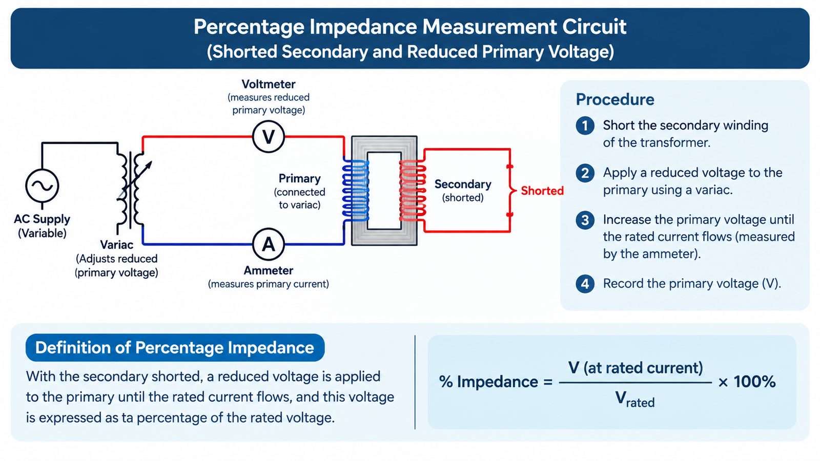
Percentage impedance (written uk%, %Z or Z%) is the fraction of rated primary voltage required to circulate rated current through the transformer when the secondary is short-circuited.
The test that defines it is straightforward in principle: short the secondary, raise the primary voltage slowly, and record the voltage at which secondary current reaches its rated value. Express that voltage as a percentage of rated primary voltage and you have uk%. It is measured at low voltage, at low flux, and it is a routine measurement for every unit — unlike the short-circuit withstand test described later, which destroys the unit if it fails.
Physically, the number is dominated by leakage reactance: the portion of the magnetic flux that does not link both windings. It depends on winding geometry, the spacing between windings and the height of the coil, not on the amount of copper in any simple way. That is why two suppliers can offer the same kVA at the same impedance and still produce different efficiency, temperature rise and short-circuit strength.
The Formula That Sets the Fault Level
For a fault at the transformer secondary terminals, the prospective symmetrical short-circuit current is:
Isc = In × 100 ÷ uk% In = kVA × 1,000 ÷ (√3 × line voltage)
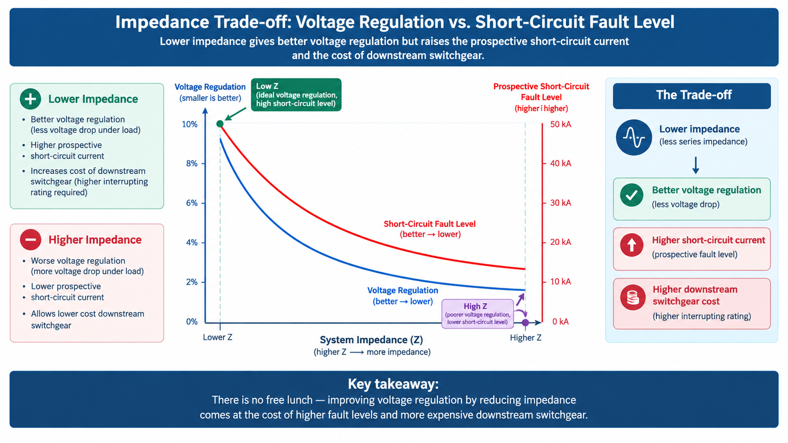
The relationship is inverse, which makes impedance the single most powerful lever on fault level. At 4% impedance the transformer delivers 25 times its rated current into a bolted fault; at 6% it delivers about 16.7 times. Halve the impedance and you double the fault current — and quadruple the mechanical forces on the windings and busbars.
Rating (kVA)
Full-load current at 400 V (A)
Isc at 4% (kA)
Isc at 6% (kA)
100
144
3.6
2.4
250
361
9.0
6.0
400
577
14.4
9.6
630
909
22.7
15.2
1,000
1,443
36.1
24.1
1,600
2,309
57.7
38.5
2,000
2,887
72.2
48.1
2,500
3,608
90.2
60.1
Two practical notes on reading this table. First, the figures assume an infinite upstream source; a real HV network has its own impedance, so the actual fault current is slightly lower, which means the table errs on the safe side for switchgear selection. Second, these are symmetrical RMS values — the first-cycle peak includes a DC offset and can reach roughly 2.5 times the symmetrical figure, which is what busbar bracing must withstand.
The cost consequence is direct: moving a 2,500 kVA unit from 6% to 4% takes the prospective fault level from 60 kA to 90 kA, and 90 kA switchgear is not a small premium over 60 kA. That single decision can outweigh the transformer price difference several times over.
Typical Impedance Values by Rating
Impedance is not arbitrary. IEC 60076-5 and the harmonised distribution standards establish conventional values by rating, and most utilities specify from this pattern:
Rating range
Typical uk%
Why this value
Up to 630 kVA
4%
Small units cannot generate dangerous fault levels, so impedance is kept low to favour voltage regulation
631 – 2,500 kVA
6%
The compromise point where fault level becomes the dominant constraint in LV switchgear selection
Above 2,500 kVA
6 – 10%
Design dependent; higher ratings need higher impedance to keep fault current within switchgear ratings
Medium and large power transformers
10 – 20%
Transmission-level fault levels would otherwise be unmanageable
Non-standard values are available on request, and are sometimes necessary — but they add cost and lead time, and they must be agreed before the LV switchgear is specified. Retrofitting a different impedance after the switchgear order is placed is not a commercial option.
Why Utilities Impose a Minimum Impedance
Where the utility sets a minimum uk%, it is protecting its own network and the customer’s switchgear. Three reasons appear repeatedly in connection agreements:
Fault level at the point of supply. The utility’s protection must be able to clear a fault at the customer’s terminals without exceeding its own equipment ratings.
Load sharing between customers on a shared feeder. A very low-impedance transformer draws a disproportionate share of fault current from the network, affecting other customers’ protection settings.
Flicker and voltage step limits. Larger motors started across a low-impedance transformer produce deeper voltage steps that propagate upstream.
If your connection offer specifies a minimum impedance, that figure overrides any general table. Confirm it before the enquiry goes out — a supplier quoting a standard 4% unit against a 6% requirement will be rejected at the design review stage, often after the switchgear has been ordered.
Voltage Drop and Regulation Under Load
The same impedance that limits fault current also causes voltage to fall as load rises. Approximate regulation can be calculated from the resistive and reactive components of impedance:
%VR ≈ loading × (ukr × cos φ + ukx × sin φ)
Where ukr = load loss in watts ÷ (10 × kVA), and ukx is derived from uk% and ukr. For a 630 kVA unit with 7,500 W of load loss, ukr is about 1.19%. At 0.85 power factor that gives:
Loading
Regulation at 4% impedance
Regulation at 6% impedance
50%
1.5%
2.1%
75%
2.3%
3.1%
100%
3.0%
4.1%
A 1.1 percentage-point difference at full load looks small, but it accumulates along the distribution chain: transformer regulation plus cable drop plus the drop at the far end of a long feeder. On a 400 V system where the total permitted drop to the last load is typically 5%, the transformer choosing 6% impedance instead of 4% can consume a visible share of that budget — and push cable sizes up to compensate.
Tap changers recover some of this. An off-circuit tap changer set on the correct tap compensates for a steady voltage offset but not for load-dependent drop; an on-load tap changer does both continuously. How the tap range and type are specified for a given supply is covered in the oil-immersed selection guide.
Parallel Operation Requires Matching Impedance
When two transformers run in parallel, load sharing is inversely proportional to their impedance: the lower-impedance unit takes the larger share. If the mismatch is significant, one unit reaches its rating while the other is still lightly loaded, and the apparent spare capacity on site does not exist in practice.
The practical rules for parallel operation:
Same vector group and phase displacement — non-negotiable; anything else produces circulating current between the secondaries.
Same voltage ratio and tap position — a small ratio difference drives a large circulating current, because the only thing limiting it is the combined impedance.
Impedance within roughly ±10% of the lower value — the usual utility requirement. Beyond that, load sharing becomes unbalanced enough to derate the pair.
Similar kVA — a ratio beyond about 3:1 makes the larger unit effectively useless at light load.
If the parallel pair is being bought together, specify the impedance in the enquiry for both units and require the routine test reports to confirm the measured values. Two units “both 6%” can differ by 10% in practice, and the tolerance in IEC 60076-1 permits it: the standard allows ±7.5% on declared impedance for the principal tapping where the declared value is 10% or above, widening to ±10% below that.
What the Short-Circuit Withstand Test Proves
Measuring uk% is a routine test. Proving the transformer survives a short circuit is a type test under IEC 60076-5, and it is a different matter entirely.
The unit is subjected to a series of full-current short circuits — typically three, at reduced voltage, with the current limited by the test laboratory’s reactor rather than by the transformer. The test verifies both thermal withstand and mechanical withstand: the windings must not deform, the impedance must not change beyond the permitted tolerance after the test, and the unit must still pass its dielectric tests.
Three things buyers should understand about it:
It is destructive if the design is inadequate. Only purpose-built short-circuit laboratories can perform it, and a failed test ends the design, not just the unit.
It is a type test, not a routine test. You receive a report for the design, not for your serial number. What you should receive with your unit is the impedance measurement, not the destructive test report.
The report must reference your configuration. A short-circuit withstand report for a different winding arrangement or rating does not qualify the design you are buying.
How the test programme is structured, what the routine test report should contain, and where to draw the acceptance limits are covered in the factory test and FAT guide.
How Impedance Interacts With Protection Coordination
Impedance sets the fault level; the fault level sets the required breaking capacity of every device downstream; and the transformer’s own damage curve sets the upper limit for the protection that sits at its terminals. Three checks follow:
Check
What it confirms
Breaking capacity of LV devices
Every breaker and fuse must exceed the prospective fault current at its installation point, using the transformer contribution plus motor contribution
Thermal withstand of cables and busbars
I²t let-through must be inside the cable’s short-circuit withstand for the clearing time
Transformer damage curve
The primary protection must clear a secondary fault before the transformer’s thermal damage curve is reached — otherwise the transformer protects the breaker instead of the reverse
This is why impedance should be fixed early. It is not simply a transformer parameter; it is an input to the protection study, the switchgear specification and the cable sizing. Change it after any of those are ordered and the whole downstream design has to be rechecked.
Choosing an Impedance for Your Project
Start with the connection agreement. If the utility specifies a minimum uk%, that is the floor.
Calculate the fault level at the required minimum. If the resulting current is within the switchgear you intended to buy, stop — the lowest compliant impedance gives the best regulation.
If the fault level exceeds the switchgear rating, either raise the impedance or buy higher-rated switchgear. Compare the two costs; for ratings above 1,600 kVA the higher impedance usually wins.
Check the regulation budget. Confirm the transformer contribution plus cable drop stays inside the permitted total at the farthest load.
If units will run in parallel, specify the impedance for the pair together and require measured values in the test reports.
The rating itself has to be settled before any of this, since impedance values are indexed to kVA. The kVA sizing method covers that calculation, and the nameplate reference shows where impedance, losses and temperature rise are declared on the plate you will receive. For dry-type units, the losses that determine ukr are also what the efficiency class regulates, so the two specifications should be written together rather than in sequence.
Conclusion
Percentage impedance is a system parameter wearing a transformer label. It sets the fault level your switchgear must survive, the voltage drop your loads will see, and whether two units can share load properly. Specify it explicitly, from the connection agreement and the fault level calculation, before the LV equipment is ordered — and ask for the measured value on your serial number, not just the design value.
If you can supply the rating, the secondary voltage and the utility’s requirement, the engineering team can confirm which impedance class keeps the fault level inside your switchgear while staying inside the regulation budget.
Frequently Asked Questions
What does 5% impedance mean on a transformer?
It means that 5% of rated primary voltage, applied with the secondary short-circuited, is enough to circulate full-load current. Practically, it means the transformer will deliver 20 times its rated current into a bolted fault at its terminals, and that its voltage will fall by roughly 3–4% at full load depending on power factor.
How do I calculate short-circuit current from transformer impedance?
Divide the full-load secondary current by the per-unit impedance: Isc = In × 100 ÷ uk%. For a 1,000 kVA transformer at 400 V, full-load current is about 1,443 A, so at 6% impedance the prospective fault current is roughly 24 kA. The result is a symmetrical RMS value and should be increased by a factor of about 2.5 for first-cycle peak when checking mechanical withstand.
Is higher or lower transformer impedance better?
Neither, in isolation. Lower impedance gives better voltage regulation and lower losses in the supply path, but raises the fault current and therefore the cost of switchgear, busbars and cable withstand. Higher impedance limits fault current and protects downstream equipment but worsens regulation and may force larger cables. The right value is the lowest one that keeps the fault level inside the equipment you are prepared to buy.
What happens if two transformers in parallel have different impedance?
Load sharing becomes inversely proportional to impedance, so the lower-impedance unit carries more than its share and can overload while the other is still lightly loaded. Common practice limits the difference to about ±10% of the lower value. Vector group and ratio must match exactly regardless; impedance matching only governs how well the pair shares load.
Does impedance change over the life of a transformer?
It should not. A measurable change in impedance indicates winding deformation, typically after a through-fault or a mechanical shock, which is why impedance is measured at commissioning and compared during later diagnostic testing. IEC 60076-5 sets a limit on the change permitted after the short-circuit withstand test for exactly this reason.
Transformer ODM and OEM programs explained: the custom engineering workflow from RFQ to FAT, the 15-field spec sheet, tooling and IP ownership, MOQ and lead-time terms.
What an efficiency class regulates, how EU ErP, DOE and GB 20052 differ, why load points are not comparable, and how to capitalise losses into a 25-year cost.