Dry Type Transformer Ratings & Nameplate: kVA, %Z, Vector Group
Published: Author: Lisa
Most transformer problems are not failures — they are mismatches between what a buyer assumed and what the rating plate actually says. Understanding dry type transformer ratings means being able to read five numbers off the plate and know exactly what they commit you to: rated capacity in kVA, percentage impedance (%Z), temperature rise, vector group, and cooling class. Everything else on the plate either describes those five or tells the service team what to buy later.
This guide decodes the standard nameplate field by field, using the IEC 60076-1 rating-plate requirements that most international dry-type units follow. By the end you should be able to check a delivered unit against its specification in about five minutes, and spot the two or three fields that most often disagree.
Why the nameplate matters more than the spec sheet
A specification sheet is a pre-production document. It states design intent. A nameplate is fixed to the unit only after it passes its routine tests, so it records as-built reality: the impedance that was actually measured, the losses that were actually recorded, the tapping range that was actually fitted. When the two disagree, the plate governs, and your protection settings, cable sizing and paralleling decisions all follow the plate.
IEC 60076-1 makes the rating plate mandatory for power transformers above 50 kVA. The reference below lists what has to be on it.
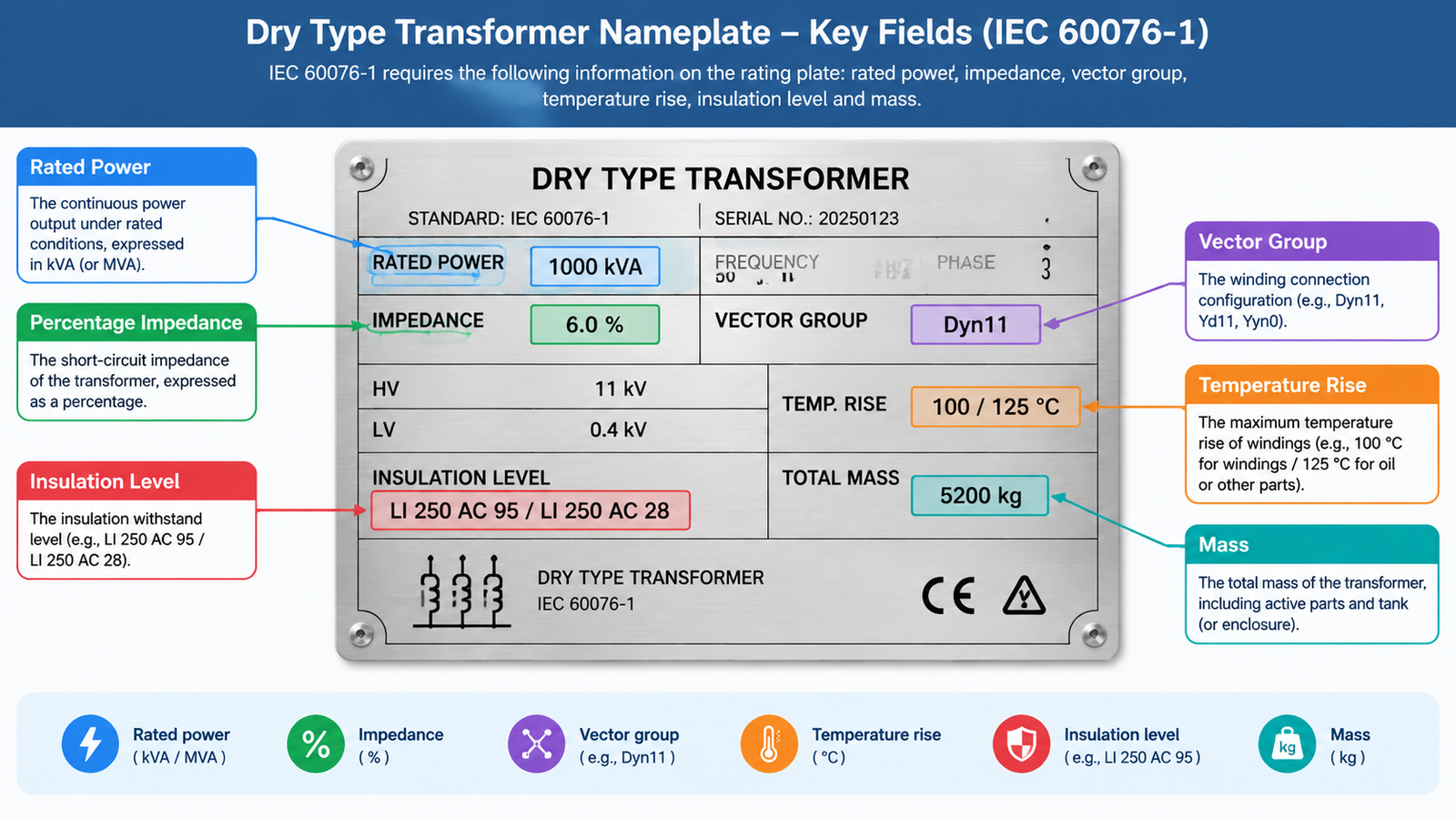
The fields IEC 60076-1 requires on a rating plate
Group
Fields
Why you care
Identity
Kind of transformer; standard and year; manufacturer name and country; serial number; year of manufacture; number of phases
Warranty tracking, spare-parts matching, customs and inspection
Power and frequency
Rated power per winding; rated frequency
Sets the continuous load the unit may carry at the declared cooling and ambient conditions
Voltage and current
Rated voltages and tapping range; rated currents per side
Confirms the ratio, and gives you the LV current that sizes cables and breakers
Impedance
Short-circuit impedance as a percentage, with its reference power
Determines fault current and how the unit shares load in parallel
Connection
Connection and phase-displacement symbol, for example Dyn11
The first thing to check before paralleling two units
Cooling and thermal
Cooling class code; guaranteed temperature rises if non-standard
Explains any dual rating, and defines how hard the insulation is being worked
Insulation
Insulation levels where the highest system voltage is 3.6 kV or above
Impulse and power-frequency withstand for coordination with your switchgear
Mass
Total mass; transportation mass if different; untanking mass for heavy units
On a dry-type unit the liquid fields disappear and three dry-type specifics appear instead: the insulation system temperature class (usually F or H), the IEC 60076-11 climatic, environmental and fire classes — commonly written as C2 E2 F1 — and an IP rating where an enclosure is fitted. Our dry type transformer specification guide covers those classes in full detail.
Rated capacity: what “kVA” actually promises
Rated power is the apparent power the transformer can carry continuously without exceeding its permitted temperature rise. The important word is continuously, and it is always conditional. A plate reading 1000 kVA is only 1000 kVA under the conditions printed beside it: the cooling class in service, the reference ambient temperature, and the installation altitude.
IEC assumes a yearly average ambient of 20 °C and a maximum of 40 °C. Put that same unit in a sealed substation room sitting at 45 °C, or above 1,000 m altitude where air density drops, and the honest capacity is lower. This is one of the most common sources of “the transformer is running hot” complaints that turn out to be a specification problem rather than a manufacturing one.
Why a dual rating appears
Units with forced cooling carry two ratings, written as a pair — for example 1,600 / 2,000 kVA AN/AF. The lower figure applies with natural air cooling only. The higher applies once fans run. Both are legitimate plate values; they simply describe two operating states. Plan your normal load around the natural-cooling figure unless you are willing to depend on fan availability.
%Z: the number that decides your protection
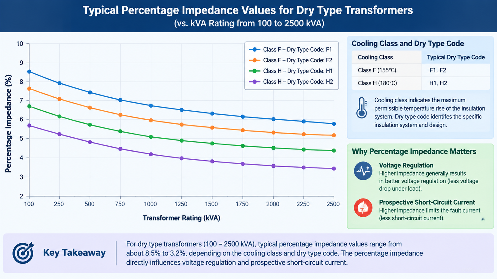
Percentage impedance, printed as something like Uk = 6%, is the voltage drop across the transformer at rated current, expressed as a percentage of rated voltage. Its practical role is twofold: it sets the voltage regulation you experience under load, and it sets the prospective short-circuit current your downstream equipment must survive.
Lower impedance means better voltage regulation and higher fault current. Higher impedance means the opposite. Typical dry-type values are 4% up to about 630 kVA and 6% from roughly 630–800 kVA upward, with 6% common across the 1000–2500 kVA range. Those values are a design convention, not a rule of nature, so the plate figure is what your protection study must use.
Impedance is also the reason two transformers of identical kVA and identical vector group can still refuse to share load evenly. Where units are paralleled, impedance must match within a few tenths of a percent, or the stiffer unit takes more than its share.
Temperature rise: the difference between AN and AF ratings
Temperature rise is the permitted temperature increase above ambient, measured by the resistance method during a temperature-rise test. It is not the same as the insulation class. A Class F (155 °C) insulation system is normally applied with a 100 K average winding rise allowance in IEC 60076-11 terms, but the guaranteed figure stamped on your plate may be lower — 80 K, for instance — if the buyer specified extra thermal margin.
A lower guaranteed rise is not free. It requires more conductor and more core material to reduce losses, so the unit is physically larger and more expensive for the same kVA. This is a deliberate trade: pay in size and cost now, gain insulation life and overload headroom later. Our dry type transformer insulation guide explains how the class letters A to H map onto those rises.
Vector group: Dyn11, Yyn0 and why paralleling fails
The vector group records the winding connections and the phase displacement between primary and secondary. In Dyn11, the HV winding is delta, the LV winding is star with a neutral brought out, and the LV phasor lags the HV by 30°. In Yyn0 both windings are star and the displacement is zero.
This matters for exactly one reason in most projects, and it is a serious one: paralleling two transformers with different vector groups produces circulating currents that can destroy both units. Matching kVA is not enough. Vector group, impedance and tap position must all line up.
Cooling class and the dry-type code
Code
Meaning
Applies to
ONAN
Oil natural, air natural
Oil-immersed baseline
ONAF
Oil natural, air forced — fans fitted
Oil-immersed with dual rating
AN
Air natural, convection only
Dry-type baseline
AF
Air forced, fans assist cooling
Dry-type with dual rating
Dry-type plates usually shorten the code to two letters because there is no liquid circuit. If a plate shows AN/AF with two kVA figures, the cooling code and the rating pair must be read together — one explains the other.
Losses and insulation level
No-load loss and load loss, both in watts, are printed on most plates and are the basis for any fair commercial comparison between offers. No-load loss is present whenever the unit is energised; load loss scales roughly with the square of the current. Where energy prices are high, the twenty-year cost of those two figures frequently exceeds the purchase price, which is why loss guarantees and their verification method deserve the same scrutiny as the kVA figure.
Insulation level appears as a pair such as LI 170 / AC 70 — a lightning impulse withstand value and a power-frequency withstand value in kV. It tells your protection engineer what surge environment the winding insulation can absorb, and it must be coordinated with the arresters and switchgear around it.
For units in the 10 kV class and similar distribution duties, the plate is usually read alongside the technical data in our 10 kV dry type transformer overview, which sets out the ratings, losses and impedance values typical for that voltage level.
A five-minute nameplate acceptance checklist
Confirm serial number and year of manufacture against the test certificates.
Check rated power and cooling class, and note whether a second rating applies.
Verify HV and LV voltages, tapping range and vector group against the purchase order.
Compare measured %Z with the specified value — a difference changes your protection settings.
Read the guaranteed temperature rise and insulation level, and file them with the asset record.
Photograph the plate on commissioning day. Plates corrode and get overpainted, and a clear photograph has rescued many urgent replacements.
If you are still comparing suppliers rather than checking a delivery, the practical starting points are the cast resin range in our SCB series dry type transformer page and the dry type transformer insulation series, both of which publish the rating fields discussed here. The dry type transformer types comparison is a useful cross-check if you have not yet settled on VPI versus cast resin.
Conclusion
Five fields do the real work on a dry-type nameplate: kVA, %Z, temperature rise, vector group and cooling class. Read them together, because each one constrains the others — a dual rating only means something when you know the cooling state, and a low impedance only looks attractive until you calculate the fault current. Check the delivered plate against the specification, keep the photograph, and send the whole plate rather than the kVA figure alone when you need a like-for-like replacement.
FAQ
What does %Z mean on a transformer nameplate?
It is the short-circuit impedance: the voltage needed to circulate rated current through the short-circuited winding, expressed as a percentage of rated voltage. It sets the prospective fault current and how well the unit shares load when paralleled.
Is 4% or 6% impedance better for a dry type transformer?
Neither is universally better. 4% gives tighter voltage regulation and higher fault current; 6% limits fault current and reduces mechanical stress on the windings. Typical dry-type practice is 4% up to about 630 kVA and 6% above that.
What kVA dry type transformer ratings are standard?
The common commercial steps are 30, 50, 100, 160, 250, 315, 400, 500, 630, 800, 1000, 1250, 1600, 2000 and 2500 kVA. Ratings above 2500 kVA are usually engineered to order. For the physical footprint at each step, see our dry type transformer sizes and dimensions chart.
Why does my nameplate show two kVA ratings?
The unit has forced cooling. The lower figure applies in natural cooling mode (AN) and the higher figure applies with fans running (AF). Plan normal operation around the lower figure unless fan availability is guaranteed.
Can I parallel transformers with different vector groups?
No. Different vector groups mean a phase displacement between secondaries, which drives large circulating currents. Vector group, impedance and tap position must all match before paralleling.
What is the difference between temperature rise and insulation class?
Insulation class is the temperature the insulation system can survive, such as 155 °C for Class F. Temperature rise is the permitted increase above ambient during operation, expressed in kelvin. The rise must always leave headroom below the class limit.
How do I read dry type transformer technical data quickly?
Start with rated power and cooling class, then voltage ratio and vector group, then %Z, temperature rise and losses. Those six values are enough to judge whether a unit suits a given project.
Routine, type and special power transformer tests under IEC 60076 explained for buyers — acceptance limits, what a FAT dossier must contain, red-flag readings and how to witness testing.
A practical 12-point checklist for auditing power transformer manufacturers in China: certifications by market, factory tests, materials, capacity and commercial terms.
How to size and specify a transformer for EV charging stations and hubs: AC input kVA, continuous load rules, demand factors, K-factor selection and site matching.