A power plant transformer is not one device. Every generating unit depends on at least three separate transformer functions, and each one is specified against a different constraint. The step-up unit moves bulk power to the grid. The unit auxiliary transformer keeps the boiler feed pumps and fans running. The station service transformer starts the plant up from cold and carries the loads that belong to the site rather than to any single unit.
Get the impedance and the tap arrangement wrong on any of them and the plant either cannot start, cannot change over between supplies without tripping the auxiliary board, or pays for the mistake in capitalised losses for thirty years. This article sets out what each of the three does, which numbers actually drive the design, and what to put in the enquiry so that tenders become comparable.
| Function |
Fed from |
Supplies |
Typical rating |
Duty |
| Generator step-up (GSU) |
Generator terminals, through the generator breaker |
The transmission or sub-transmission network |
Equal to generator MVA, 100 MVA to over 1,000 MVA |
Continuous at full load whenever the unit runs |
| Unit auxiliary transformer (UAT) |
Generator terminals, tapped before the generator breaker |
The unit board: boiler feed pumps, fans, mills, condensate pumps |
About 10-12% of generator MVA for steam units, under 1% for hydro and gas turbines |
Continuous while the unit runs, near full load |
| Station service transformer (SST) |
The high-voltage network, independently of the unit |
Start-up power, common station loads, and a diverse supply for critical drives |
50-60 MVA for a four-unit fossil or nuclear station |
Light and intermittent, half load or less for most of its life |
Unit transformer, unit auxiliary transformer: the naming trap
Before any technical discussion, fix the vocabulary, because the same phrase means opposite things in different markets. In North American practice the step-up unit is the generator step-up transformer and the auxiliary unit is the unit auxiliary transformer. In older British and Indian practice the step-up unit is the generator transformer, and the phrase “unit transformer” is used for the auxiliary unit.
A specification that says “unit transformer, 40 MVA, 15/6.6 kV” is unambiguous once the voltage ratio is read. One that says “unit transformer, 40 MVA” is not. Put the function name, the source voltage and the load board voltage on the first line of the enquiry. It costs one sentence and prevents a tender for the wrong machine.
How the three fit together
The arrangement is simple once you see it as two independent paths into the same auxiliary board. The unit path takes power from the generator before that power leaves the plant. The station path takes power from the transmission network. Normal running is on the unit path, because it avoids paying transmission losses and network charges on your own auxiliary load. Start-up and shutdown are on the station path, because the generator is not available.
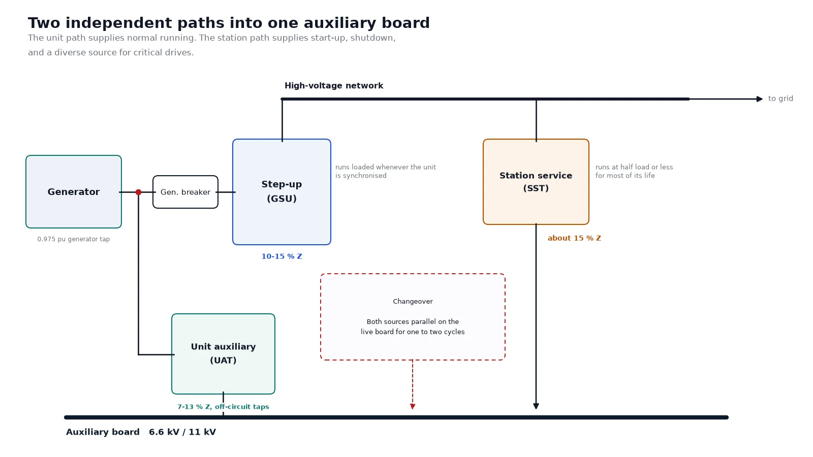
Two details in that diagram matter more than the rest. The unit auxiliary transformer is tapped between the generator terminals and the generator circuit breaker, so it stays energised whenever the generator is synchronised, even if the generator breaker opens. And the changeover between the unit supply and the station supply is made on the auxiliary board while the board is live. That changeover is the reason the station transformer’s impedance is not a free choice.
The unit auxiliary transformer
The UAT is sized from the actual running auxiliary load of the unit plus a margin of about 10%. Where two UATs are installed for redundancy, each is rated at a minimum of 55% of that running load, so that one unit can carry the board alone if the other is out of service.
Why the primary is not at generator nominal voltage
Common practice is to rate the UAT primary at about 0.975 per unit of the generator terminal nameplate voltage, with a small overvoltage capability on top. The reason is that a loaded generator does not sit at nameplate voltage. Terminal voltage sags under reactive load and rises when the unit is lightly loaded. Rating the UAT slightly below the generator’s nominal voltage keeps the auxiliary board at its nominal voltage across the normal operating band, instead of forcing the board high and running every motor slightly over-fluxed.
Taps, vector group and earthing
Off-circuit taps of plus or minus 2.5% and 5% on the high-voltage side are the usual arrangement. These are set once at commissioning, against the measured generator voltage, and never touched again. A UAT with an on-load tap changer is rare and usually a specification habit carried over from the station transformer; it adds a failure mode on a machine that has no need of one.
The winding is normally delta on the high-voltage side and star on the low-voltage side, with the star neutral earthed through a resistor sized to limit earth-fault current on the auxiliary board. That resistor, not the transformer, sets the earth-fault protection settings for the board, so its value belongs in the same enquiry.
The station service transformer
The station transformer carries three jobs that have nothing in common except that they all happen when the unit is unavailable. It supplies the start-up sequence: the boiler feed pump, the forced draught fan, the air preheater and the control and instrumentation load have to run before the generator can be synchronised. It carries the common station loads that no single unit owns — lighting, cranes, workshops, coal handling, circulating water pumps. And it provides a diverse second source to drives that are duplicated per unit, so that a fault on one unit board does not take out a service the whole site depends on.
A minimum of two station transformers is normal, so that the site retains a supply with every unit shut down. On a four-unit station each may be rated to start two units simultaneously while carrying a share of the station load, which is why the station transformer is often larger than the unit auxiliary transformer it backs up.
It is also, in practice, the first major connection a station makes to the transmission system, because construction and commissioning power has to come from somewhere. That single fact drives the tap range: during commissioning the network is not yet at its final strength and the voltage may sit well below nominal for months.
Why the impedance is around 15%
Here is the number that surprises people. The station transformer’s impedance is not selected to limit load-side faults in the ordinary sense. It is selected so that the station supply and the unit supply can be paralleled momentarily on the auxiliary board during changeover, without the combined fault current exceeding the rating of the board’s switchgear.
During that changeover both sources feed the board. The fault level at the board is the sum of what each source can deliver, so the station transformer has to be relatively soft. Values around 15% are typical for that reason alone. If you reduce the impedance to improve motor starting, you will very likely exceed the switchgear rating the moment the two sources are paralleled.
Why it has an on-load tap changer
The UAT sees a generator whose voltage is controlled by the excitation system, so it needs only fixed taps. The station transformer sees a transmission bus whose voltage moves with network conditions, and it has to deliver a stable auxiliary board voltage during start-up when the bus may be low. An on-load tap changer of plus or minus 10% in steps of 1.25% on the high-voltage side is the standard answer.
Connection is normally star-star, because both the high-voltage and the low-voltage winding need a neutral brought out for earthing. Older designs added a delta tertiary to absorb third-harmonic current; with modern three-limb cores and the fault levels now involved, that tertiary is often omitted, because it also raises the fault level the board has to withstand.
Impedance is the number that decides everything
For the UAT, the impedance sits inside a window bounded from below by the switchgear and from above by motor starting. The lower bound is fault current: the short-circuit capacity at the auxiliary board is the transformer rating divided by its per-unit impedance, so a lower impedance means a higher fault current and a more expensive board.
The upper bound is voltage dip. When the largest motor on the board starts direct-on-line, the dip at the board is approximately the per-unit impedance multiplied by the ratio of starting kVA to transformer rating. The usual acceptance criterion is that the voltage at the motor terminals does not fall below 80% of rated with the rest of the plant running.
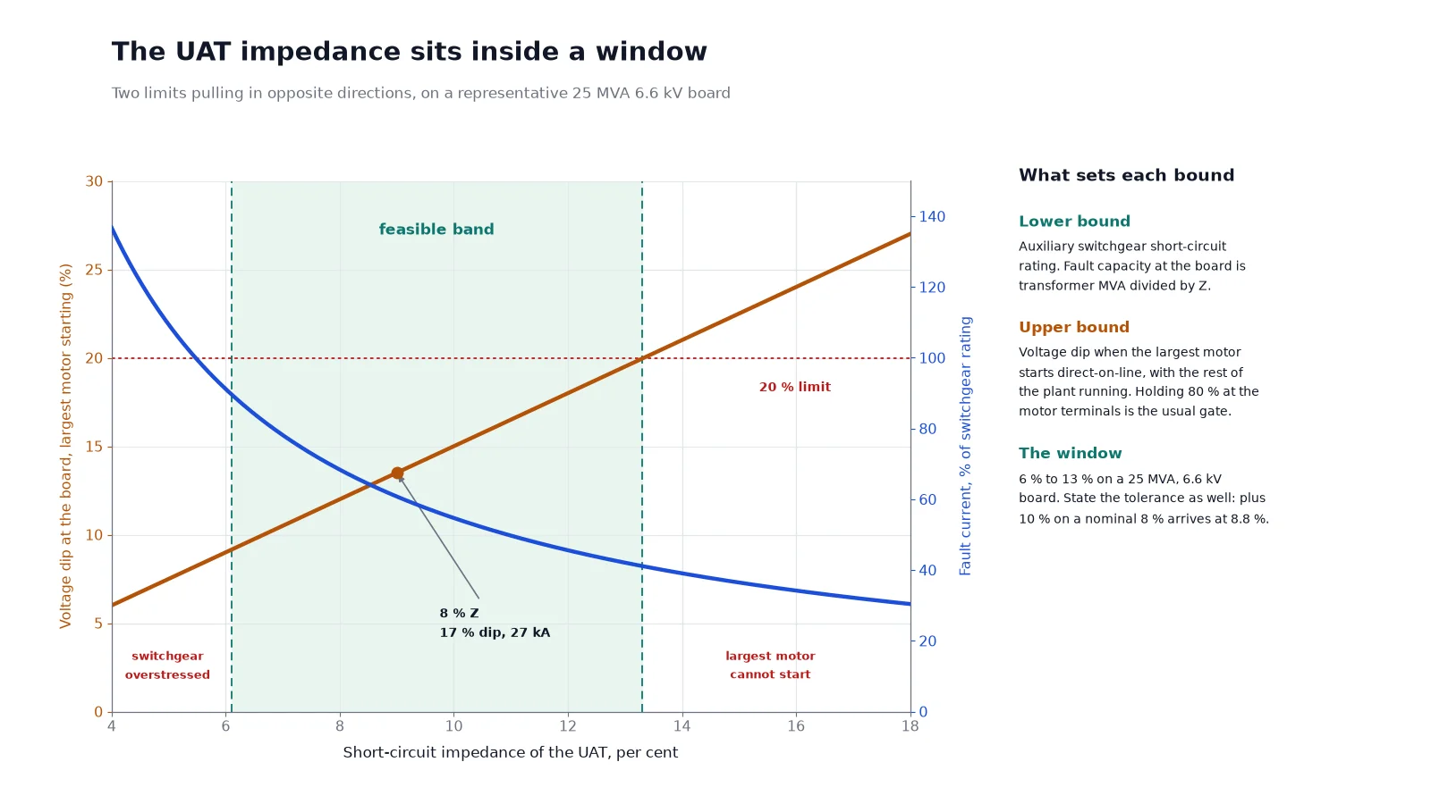
The dashed lines in that figure are the two limits for a representative 25 MVA, 6.6 kV board with a largest motor starting at roughly 150% of transformer rating and switchgear rated well above the transformer. The feasible band sits between about 7% and 13%. Below the band the board’s switchgear is overstressed; above it the largest motor cannot start without dragging the board down.
Two practical notes. First, specify the impedance tolerance. A nominal 8% with a plus 10% tolerance can arrive at 8.8%, and the coordination study that cleared the board was done at 8%. Second, remember that the step-up transformer is designed against a completely different objective — system fault level, transformer cost and transient stability — and typically lands between 10% and 15% on its own base. Do not carry numbers across from one function to another. The underlying physics is set out in our guide to transformer impedance and short-circuit voltage drop.
Cooling, and the ONAN rating you must state
Auxiliary transformers are usually ONAN/ONAF, with fans that start on winding temperature or on load. The contract number that matters is the ONAN rating as a percentage of the forced-cooled rating: 50% for a UAT, 60% for a station transformer is common.
That percentage is a reliability requirement, not a marketing figure. If the fans fail, or the auxiliary power to the fans fails, the transformer must still carry the essential auxiliary load at reduced output until the unit can be shut down in an orderly way. A 50 MVA ONAF unit with a 50% ONAN rating delivers 25 MVA with the fans stopped. If the specification omits the number, a tenderer may deliver a unit whose ONAN rating is 67%, and the plant loses a contingency it thought it had bought. The conventions are explained in transformer cooling classes ONAN to ODAF.
Loss evaluation: where a power plant differs from a factory
Industrial buyers compare purchase price. Power plant buyers capitalise losses, because an auxiliary transformer runs about 8,640 hours a year and its losses are billed at the plant’s own cost of generation.
The capitalised cost of no-load loss, usually called A, is the present value of one kilowatt of core loss over the transformer’s life. It is built from the operating hours, the mid-life energy cost and an annuity factor for the discount rate. The capitalised cost of load loss, B, is A multiplied by the square of the load factor, because load loss rises with the square of current.
Typical values run from about USD 3,000 to 8,000 per kW for A and USD 800 to 2,000 per kW for B, rising with energy cost. Offshore and islanded plants sit at the top of those ranges because every dissipated kilowatt must also be removed by the cooling system.
| Parameter |
Unit auxiliary transformer |
Station service transformer |
| Load factor over life |
High, close to rated whenever the unit runs |
Low, at or below half load for most of its life |
| Loss that dominates the evaluation |
Load loss, weighted by B |
No-load loss, weighted by A |
| Design consequence |
More copper, lower current density, sometimes forced cooling at a lower temperature |
Better core grade, lower flux density, thinner laminations |
| Common specification error |
Applying the plant’s A factor to both loss components |
Buying a low load-loss design that is never recovered |
Worked example. A 40 MVA station transformer with 22 kW of no-load loss and 180 kW of load loss, evaluated at A of USD 5,000 and B of USD 1,200 per kW, carries a capitalised loss cost of USD 110,000 plus USD 216,000, or USD 326,000. On a unit that costs perhaps USD 600,000, the losses are worth more than half the purchase price. The same 40 MVA machine used as a UAT, running near rated load, would weight the load-loss term very differently.
This is the single most useful thing a plant buyer can put in the enquiry: state A and B. A tender that is not evaluated against stated loss rates is a tender for the cheapest transformer, not the cheapest outcome.
Oil-immersed or dry-type for plant auxiliaries
The great majority of plant auxiliary and station service transformers are oil-immersed, on size and cost. Cast resin earns its place where the fire case is unacceptable or the space is small: cable spreading rooms, turbine hall low-voltage boards, hydro stations where the transformer sits inside the dam gallery, and nuclear safety-related areas where oil is excluded from the fire analysis altogether.
Where a dry-type unit is used, the same three numbers apply — impedance, ONAN rating and the loss weighting — but the thermal limits change, and the specified temperature rise class becomes the controlling parameter. Both families are catalogued under oil-immersed power transformers and dry-type power transformers.
How the arrangement changes with plant type
A coal or nuclear steam station follows the classic pattern: one step-up unit, two unit auxiliary transformers and two station transformers, with the auxiliary load at 5 to 8% of gross generation.
A combined-cycle gas plant breaks the pattern, because its auxiliary load is around 1% or less. Designing a 10 MVA station transformer for a 400 kV connection is technically awkward and commercially poor. The usual answer is a generator switch or generator circuit breaker with a tap taken from the low-voltage side of the step-up transformer, which then doubles as the station supply while the unit runs. One transformer is saved, and the difficult small-rating high-voltage design disappears with it.
Hydro stations are similar. The unit auxiliary load is a fraction of a percent of generator rating, so a dedicated UAT is often not justified at all; station service is carried from the unit board through a tap on the step-up transformer.
Solar and battery plants have no generator and therefore no unit auxiliary transformer. What remains is a station service function serving tracker drives, inverter auxiliaries, SCADA, and — on battery sites — the thermal management of the containers. That last load, not motor starting, is what sizes the auxiliary transformer, and it behaves very differently from a boiler feed pump. Our solar PV and battery storage transformer guide covers that case.
Earthing practice for the auxiliary board changes with the plant’s overall grounding philosophy, and it is worth settling before the transformer winding is fixed, since the transformer’s neutral arrangement is part of that decision. See medium-voltage neutral grounding methods.
What to put in the enquiry
- Function: step-up, unit auxiliary, or station service. State it in words.
- Source voltage and its normal operating band, including the 0.975 per-unit generator rating if the unit is a UAT.
- Auxiliary board voltage, and the board’s short-circuit withstand rating in kA.
- Largest motor rating and starting method, and the acceptable voltage dip at the motor terminals.
- Impedance, plus the tolerance. Not the impedance alone.
- Tap type, range and step. Off-circuit for a UAT, on-load for a station transformer.
- Cooling classes and the ONAN rating as a percentage of the forced-cooled rating.
- Loss caps for no-load and load loss, and the A and B capitalisation rates for evaluation.
- Vector group, LV neutral treatment and the earthing resistor value.
- Site ambient, altitude, seismic level, pollution level, and transport weight and height limits.
Item five and item ten are the two that most often arrive late and cost the most to fix. A transformer that cannot be moved to site has to be redesigned, and an impedance tolerance that was never stated cannot be enforced. Both are verified at the factory acceptance test, which is the point at which they become expensive — our guide to power transformer factory acceptance testing sets out what to witness and what to record.
Common mistakes
- Using “unit transformer” without a voltage ratio, so the tender answers the wrong question.
- Setting the station transformer impedance by load-flow habit rather than by the changeover fault level, then discovering the board cannot be paralleled.
- Leaving the ONAN rating as a percentage unstated and receiving a unit with no fan-failure contingency.
- Specifying an on-load tap changer on a UAT, where it adds cost and a failure mode with no operating benefit.
- Applying a single set of loss capitalisation factors to both the UAT and the station transformer, which optimises the wrong machine.
- Forgetting that the station transformer is also the construction power supply, and specifying a tap range that cannot cope with a weak commissioning network.
Frequently asked questions
What is the difference between a unit transformer and a unit auxiliary transformer?
The naming is regional. In North American practice the unit auxiliary transformer feeds the unit’s own auxiliary board from a tap on the generator terminals, while the step-up unit is called the generator step-up transformer. In British and Indian practice the step-up unit is the generator transformer and “unit transformer” often refers to the auxiliary unit. Always confirm the function by reading the voltage ratio, not the name.
Why is the station service transformer impedance higher than the unit auxiliary transformer?
Because the two sources are paralleled momentarily on the auxiliary board during every changeover. The fault level at the board during that moment is the sum of both sources, so the station transformer must be relatively soft to keep the combined current inside the switchgear rating. Around 15% is typical, against 7% to 13% for the unit auxiliary transformer.
What size is a power plant auxiliary transformer?
For a steam unit, the unit auxiliary transformer is roughly 10% to 12% of generator MVA, sized from the measured running auxiliary load plus 10%. For hydro and gas turbine units the auxiliary load is around 1% or less, and a dedicated unit auxiliary transformer is often omitted. A station transformer for a four-unit fossil or nuclear station is commonly 50 to 60 MVA.
Can a dry-type transformer be used in a power plant?
Yes, and it frequently is, but usually at low voltage in cable rooms and switchrooms, or where the fire case rules oil out entirely. Above a few MVA the oil-immersed unit is smaller, cheaper and easier to repair, and the cooling behaviour is more forgiving of the intermittent overloads that auxiliary boards produce during start-up.
What impedance should I specify for a unit auxiliary transformer?
Specify the impedance that satisfies both limits and state both in the enquiry. The lower limit comes from the auxiliary board’s short-circuit withstand; the upper limit comes from the acceptable voltage dip when the largest motor starts with the rest of the plant running. For a typical 25 MVA, 6.6 kV board the feasible band falls between about 7% and 13%. Always add a tolerance, typically plus or minus 7.5% to 10%.
The practical summary
Three transformers, three different design drivers. The step-up unit is driven by system fault level and loss cost. The unit auxiliary transformer is driven by motor starting against switchgear rating. The station service transformer is driven by the need to parallel with the unit supply during changeover, and then by a load factor low enough that its no-load loss matters more than its load loss.
If you are specifying auxiliary or station service transformers for a new unit or a retrofit, send us the auxiliary board fault rating, the largest motor and its starting method, and your A and B loss rates. Those three inputs fix the impedance, the cooling and the economic optimum before a single drawing is issued. Our power transformer applications guide covers the rest of the plant types, and the team can quote against a full datasheet at Kampa Electric.