How you ground the neutral of a medium-voltage system decides three things at once: how much current flows during a single line-to-ground fault, how much voltage stress the healthy phases see while that fault is present, and whether the plant keeps running or shuts down. There is no universally correct answer — a method that is standard practice in a 6.6 kV Chinese industrial park is often unacceptable in a 13.8 kV North American process plant, and both are defensible for their own networks.
This guide covers the five grounding methods used on MV systems, the grounding transformer that makes two of them possible where no neutral exists, the sizing arithmetic, and the selection logic that links the method to the application. It is written for the engineer or buyer who has to specify a grounding arrangement, not just name one. For the protection schemes that go with it, see power system protection.
Why the Neutral Needs a Deliberate Connection
An ungrounded system is not actually ungrounded — it is capacitively coupled to earth through the insulation of every phase conductor. That capacitance provides a path, and the impedance of that path sets the fault current. Because the path is uncontrolled, so is the fault current, and so is the overvoltage that appears on the healthy phases when an arcing ground fault restrikes.
Introducing a deliberate connection gives you control. Depending on what you insert between neutral and earth — nothing, a resistor, a reactor, or an open circuit with monitoring — you choose between a large fault current that trips fast and a small one that can be tolerated while the fault is located. That trade is the whole subject.
The Five Methods Compared
Method
Typical earth-fault current
Healthy-phase voltage during fault
Supply continuity
Typical voltage range
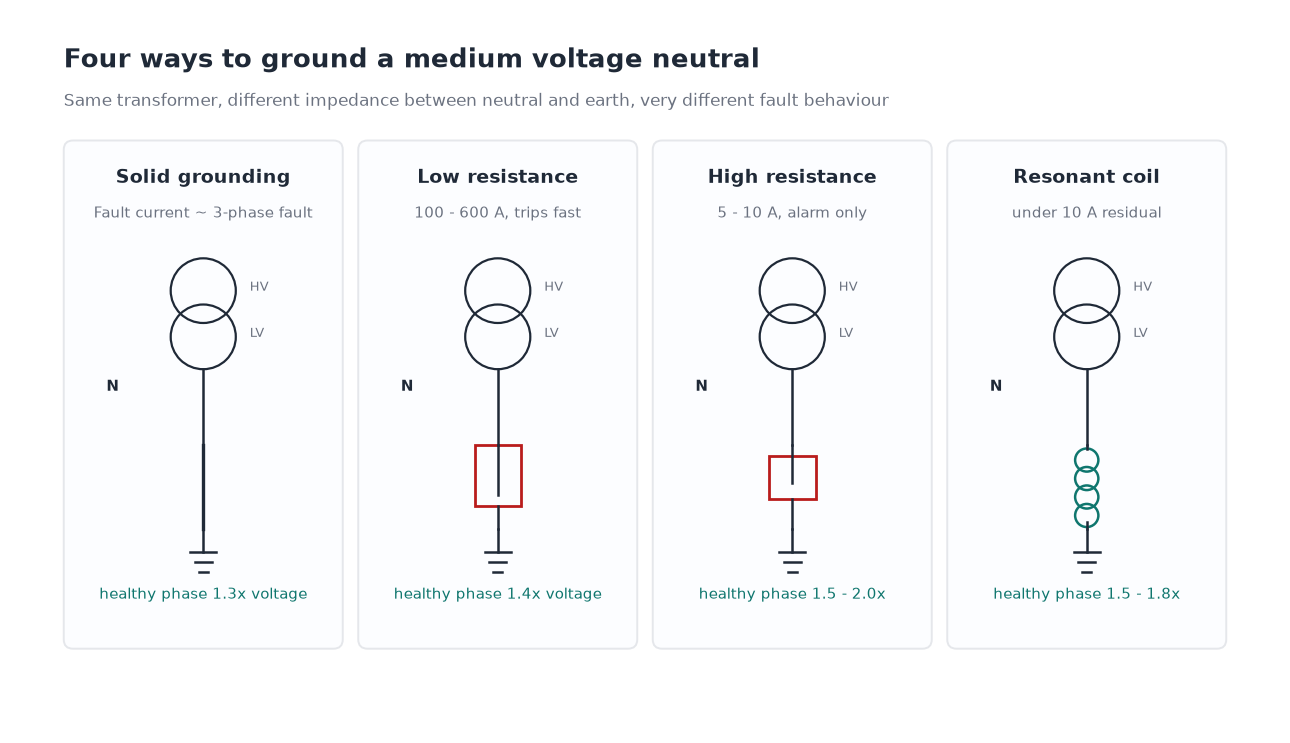
Solid (effectively) grounded
60% to 100%+ of three-phase fault
About 1.3× normal
Fault trips immediately
All MV levels, transmission
Low resistance grounded
100 to 600 A
About 1.4× normal
Fault trips, usually fast
2.4 to 15 kV industrial
High resistance grounded
5 to 10 A
1.5 to 2.0× normal
Alarm only, fault located live
480 V to 15 kV, critical process
Resonant (arc suppression coil)
Under 10 A residual
1.5 to 1.8× normal
Often allowed to run for hours
6 to 35 kV distribution
Ungrounded (isolated neutral)
Capacitive only, typically under 10 A
Up to 1.9 to 3.0× normal
Alarm, but high overvoltage risk
Small systems, auxiliary supplies
The voltage multipliers in that table are typical values conditioned on the zero-sequence to positive-sequence reactance ratio, not fixed constants. A system described as “effectively grounded” in the IEEE sense has X0/X1 below 3 and R0/X1 below 1, which is what holds the healthy-phase voltage near 1.3×. Change the grounding impedance and the multiplier moves.
Solid Grounding
The neutral is connected directly to earth. Line-to-ground fault current approaches the three-phase fault current, so the fault is detected by any over-current element and cleared in the first zone. Insulation is stressed the least of any method, which allows lower basic impulse levels and cheaper insulation coordination across the whole network.
The cost is that a single line-to-ground fault is a full-scale short circuit. Switchgear, cables and transformers must be rated for it, and the fault energy is at its maximum. Solid grounding is the right answer where the network is large, the fault level is already high, and the equipment is rated accordingly — most transmission systems and many large industrial distribution networks with their own generation.
Low Resistance Grounding
A resistor limits the earth-fault current to a defined value, typically between 100 A and 600 A. The fault is still detected and cleared quickly, but the current is low enough that damage at the fault point — cable insulation, motor windings, switchgear arc flash energy — is materially reduced. This is the reason LRG dominates industrial MV systems in the 2.4 kV to 15 kV range.
The choice of current value is a compromise. A higher current gives a more reliable, easier-to-detect fault signature and less risk of a high-resistance fault going undetected. A lower current gives less damage and less arc flash energy. Values around 200 to 400 A are common because they satisfy both. The resistor is rated for the fault current for a defined time — typically 10 seconds — and its short-time rating is a specification item, not an afterthought.
High Resistance Grounding
A resistor limits the earth-fault current to around 5 to 10 A — low enough that the fault can be left in place while it is located and the process continues. This is why HRG is standard in continuous-process plants: pulp and paper, petrochemical, semiconductor, and anything where an unplanned trip costs more than the fault.
HRG carries two obligations that are frequently underspecified. First, the system must have an insulation level that tolerates the higher healthy-phase voltage for as long as the fault persists, and that means the whole network, not just the new switchgear. Second, the fault must actually be found — HRG without a pulsing or tracing system is a way of deferring a trip, not avoiding it. A pulsing contactor or a signal-injection unit is part of the package, not an accessory.
HRG is normally applied where the system charging current is low enough that a 5 to 10 A resistor dominates it. Once the natural capacitive current approaches the resistor current, the method loses its predictability and a resonant system becomes the better answer.
Resonant Grounding and Arc Suppression Coils
A variable reactor — the arc suppression coil, or Peterson coil — is connected between neutral and earth and tuned so that its inductive current cancels the capacitive earth-fault current of the network. The residual current at the fault point then falls to a few amps, which is often below the level needed to sustain an arc. Many transient ground faults self-extinguish, and the supply continues without an outage.
This is why resonant grounding is dominant in 6 kV to 35 kV distribution networks across Europe and Asia. The tuning has to track the network configuration, because adding or removing cable changes the capacitance; automatic tuning controllers do this continuously by injecting a signal and measuring the system response.
The costs are complexity and a slower fault clearance. A sustained fault in a resonant-grounded system may be carried for hours, which requires the network insulation to be rated for the voltage rise and requires a fault-location method that works at low current. It also means the protection settings are fundamentally different from those of a resistance-grounded system, since over-current elements will not see the fault at all.
Ungrounded Systems
With no deliberate neutral connection, the only earth-fault path is the phase-to-earth capacitance. Fault current is small, so a single ground fault does not require a trip — but the overvoltage during intermittent arcing can reach two to three times normal phase voltage, and that is what damages insulation and eventually produces a second fault on a different phase. Two simultaneous ground faults on different phases are a phase-to-phase short circuit through earth, with full fault current and no controlled clearing.
Ungrounded operation survives in small systems — auxiliary supplies, control power, some marine installations — where the capacitance is low and the overvoltage risk is accepted. For anything larger, one of the other four methods is a better trade.
Grounding Transformers: Creating a Neutral Where There Isn’t One
Delta-connected transformer windings have no neutral, and neither do some generator or motor circuits. Two of the methods above require one, which is where the grounding transformer comes in — usually a zig-zag winding, sometimes a Y-delta bank with the delta closed.
The grounding transformer carries no load. In normal operation only a small magnetising current flows. During a ground fault it carries the fault current for the duration the resistor or relay allows, and its short-time thermal rating — 10 seconds or 1 minute is typical — is what sizes it. The continuous rating is often much smaller than the short-time rating, which confuses buyers who compare it against a distribution transformer of similar kVA.
Should the requirement be for a neutral that also supplies station power, the grounding transformer can be built with a secondary winding, in which case it becomes a station service transformer with a grounding function. Where there is no need for a neutral at all, the alternatives and their trade-offs are set out in the power transformer guide.
Sizing the Resistor and the Grounding Transformer
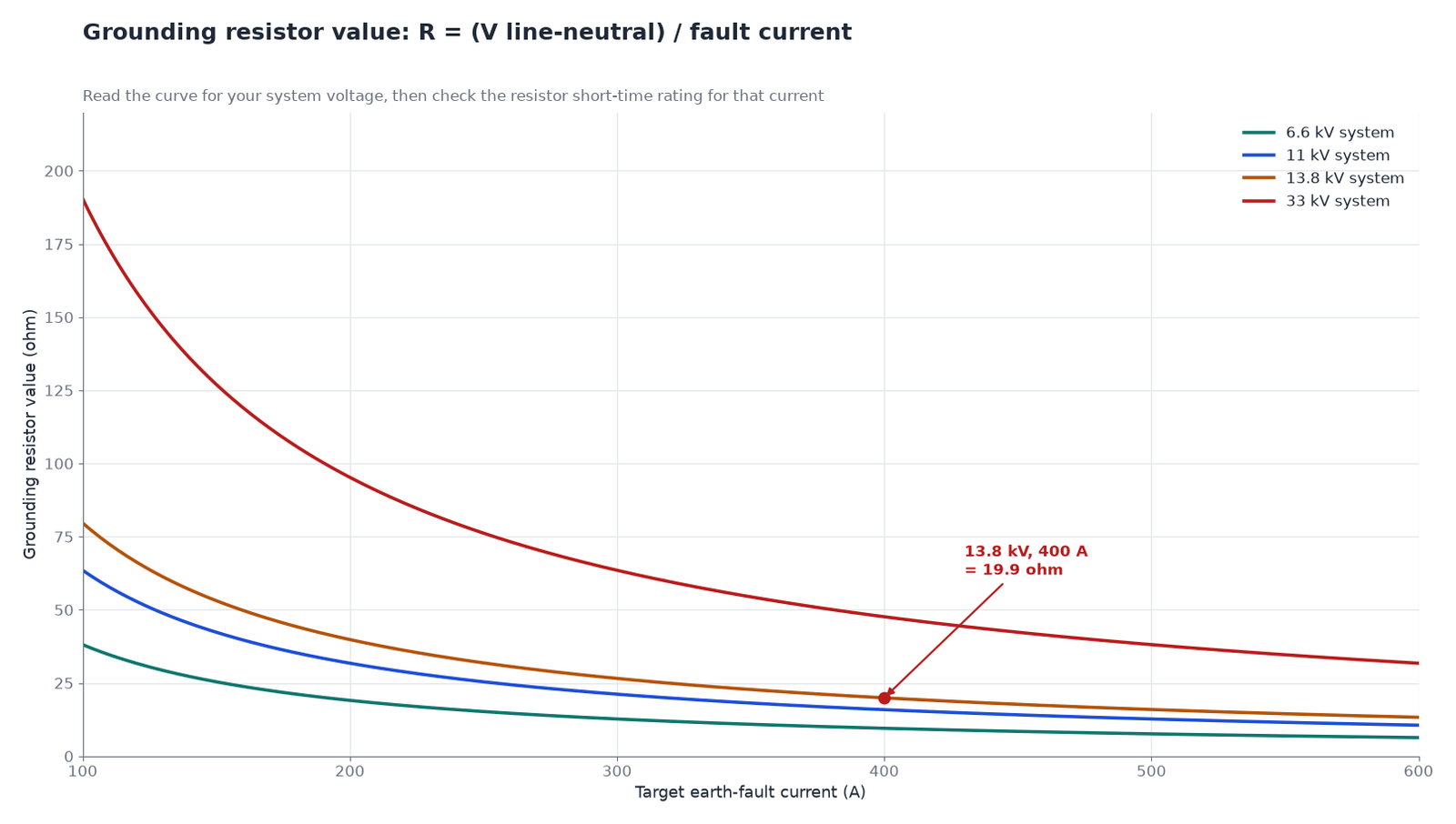
The arithmetic is short. Choose the fault current you want, then divide the line-to-neutral voltage by it.
R = VL-N / Ifault, where VL-N = VLL / √3
For a 13.8 kV system with a target fault current of 400 A: line-to-neutral voltage is 7,968 V, so the resistor is 7,968 / 400 = 19.9 Ω. Its short-time power dissipation is 7,968 × 400 = 3.19 MVA for the rated duration. The resistor element is specified by resistance, current and time, not by continuous watts.
System voltage
Target fault current
Resistor value
Short-time duty
6.6 kV
200 A
19.1 Ω
1.32 MVA, 10 s
11 kV
300 A
21.2 Ω
3.18 MVA, 10 s
13.8 kV
400 A
19.9 Ω
3.19 MVA, 10 s
33 kV
300 A
63.5 Ω
10.9 MVA, 10 s
The grounding transformer is then sized to carry that current on its neutral for the same duration, with a continuous rating sufficient for the unbalanced load it may see and for the third-harmonic current that circulates in a zig-zag winding. Impedance matters too: the zero-sequence impedance of the grounding transformer adds to the resistor and reduces the actual fault current below the calculated value, which is why the specification should state whether the target current is before or after that impedance. The same impedance relationships govern short-circuit behaviour generally, as covered in the article on transformer impedance and short-circuit voltage drop.
Choosing the Method by Application
Application
Preferred method
Reason
Large industrial plant with own generation
Low resistance, 200–400 A
Fast clearance with reduced fault damage
Continuous process, unplanned trip is costly
High resistance, 5–10 A
Alarm-only operation while fault is traced
MV distribution overhead network
Resonant, auto-tuned
Self-extinguishing transient faults
Cable-heavy urban distribution
Resonant or low resistance
High charging current needs tuning or defined current
Data centre MV distribution
Low resistance, with HRG considered
Selectivity with downstream protection
Auxiliary and control supplies, small systems
Ungrounded with monitoring
Low capacitance, acceptable overvoltage risk
Network with no accessible neutral
Zig-zag grounding transformer plus resistor
Creates a neutral without a delta reconnection
The voltage class of the network interacts with all of this: the same nominal “medium voltage” covers insulation levels and standard practices that differ by region, as the comparison of 10 kV, 11 kV and 13.8 kV voltage classes sets out. A specification written for one region does not transfer unchanged to another.
Verification and Commissioning
Grounding equipment is easy to install wrongly and hard to notice afterwards. The checks worth insisting on are: a resistance measurement of the resistor at installation, not just at the factory; a polarity and ratio check on the grounding transformer; a primary injection test that confirms the relay sees the intended earth-fault current; and a functional test of the alarm or trip path, including the pulsing system if HRG is used. The test programme that covers these items is described in the factory acceptance test guide and, for the wider protection scheme, in the material on industrial power distribution and protection.
Conclusion
Choose the grounding method by asking what a single line-to-ground fault should do: trip instantly with minimum equipment stress, trip with reduced damage, alarm and wait, or self-extinguish. That answer sets the current target, the current target sets the resistor or coil, and the resistor sets the grounding transformer rating. Everything after that — insulation coordination, relay settings, fault location equipment — follows from the same decision. Where the network has no neutral, the transformer range includes zig-zag grounding units built for short-time duty.
Frequently Asked Questions
What is a neutral grounding transformer?
A transformer whose only job is to provide a neutral point on a system that does not have one, typically a zig-zag winding connected between the phase busbars and earth, with a resistor or reactor between its neutral and earth to limit ground-fault current.
What is the difference between low resistance and high resistance grounding?
Low resistance grounding limits fault current to roughly 100–600 A so the fault trips quickly with reduced damage. High resistance grounding limits it to 5–10 A so the system can keep running on alarm while the fault is located.
Why is resonant grounding used on 6–35 kV systems?
Because the arc suppression coil cancels the capacitive fault current, letting transient ground faults self-extinguish. Most faults on overhead MV networks are transient, so the supply continuity benefit is large.
How do I calculate the grounding resistor value?
Divide the line-to-neutral voltage by the desired fault current. For a 13.8 kV system and 400 A target, 7,968 V / 400 A gives 19.9 Ω.
Can a delta-connected system be resistance grounded?
Yes, by adding a zig-zag grounding transformer to create a neutral, then connecting the resistor to that neutral. No reconnection of the main transformer is required.
What happens if a high resistance grounded system has two ground faults?
The two faults form a phase-to-phase path through earth, producing full fault current with no current-limiting resistor in the circuit. This is why HRG systems require fast fault location rather than indefinite tolerance.
Step-up and step-down oil-immersed transformers differ in taps, impedance, cooling and loss weighting. Here is how to specify each duty for generation and distribution.
Why partial discharge decides cast resin transformer life: the 10 pC limit, how the IEC 60270 test runs, what the pC reading means, and the casting defects behind it.
Decode CT accuracy classes: metering classes 0.1 to 3.0, what the S suffix changes, how 5P10 and 10P10 differ, and why burden decides the accuracy you actually get.