Neutral Grounding Methods for MV Systems
Compare solid, low resistance, high resistance, resonant and ungrounded MV neutrals, and size the grounding transformer and resistor that go with each method.
Read More

Oil-immersed step-up and step-down transformers are the same machine working in opposite directions, and the difference between them is almost never the iron and copper. It is the tap arrangement, the insulation coordination, the cooling design, the impedance target and the protection scheme — all of which are set by which side faces the network and which side faces the load or the generator. Buy the wrong configuration and the unit will run, but it will run outside its intended operating envelope.
This guide separates the two duties, shows what changes in the specification, and gives the selection logic for the two applications where the distinction matters most: renewable generation step-up and substation distribution step-down. The starting point for the hardware is the oil-immersed power transformer range.
A step-up transformer takes a lower voltage on its primary and delivers a higher voltage on its secondary. A step-down transformer does the reverse. Both obey the same turns ratio relationship, and a given unit can physically operate in either direction — power flows from the higher-voltage winding to the lower one or the other way round depending on where the source is.
What the label really describes is the design intent. In a step-up unit the low-voltage winding is the input, connected to a generator or an inverter, and the high-voltage winding faces a transmission or sub-transmission network. In a step-down unit the high-voltage winding is the input, connected to the network, and the low-voltage winding feeds distribution. That difference in role drives every subsequent design decision.
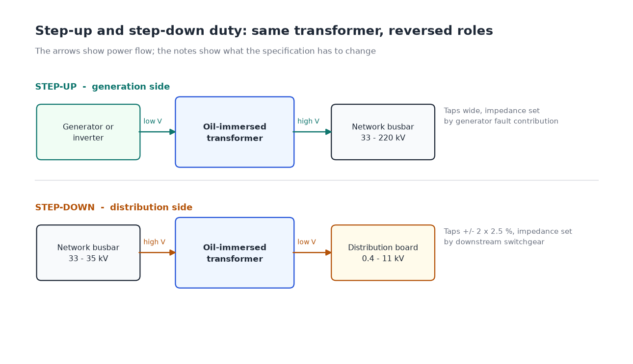
| Design item | Step-up (generation side) | Step-down (distribution side) |
|---|---|---|
| Tap changer location | On the HV winding, wider range to track grid voltage | On the HV winding, typically ±2 × 2.5% |
| Tap changer type | Off-circuit or on-load, depending on grid code | Off-circuit for distribution; OLTC for substation |
| Impedance target | Chosen to limit generator fault contribution | Chosen to coordinate with downstream protection |
| Vector group | YNd11 common; generator earthing considered | Dyn11 common for distribution |
| Cooling | ONAN/ONAF with forced cooling for summer peaks | ONAN, ONAF where load is dense |
| Loss evaluation | Losses capitalised over high utilisation hours | Losses capitalised over load profile |
| Protection emphasis | Generator and transformer differential, over-fluxing | Over-current, earth fault, Buchholz, pressure relief |
| Voltage ratio | Often non-standard, e.g. 0.69/35 kV | Standard, e.g. 35/0.4 kV, 33/11 kV |
Everything in that table is a consequence of one question: which winding sees a stiff network and which sees a source with its own impedance. A generator has subtransient reactance that limits fault current and produces voltage distortion; a distribution network does not. The transformer has to be specified for the reality on each side.
Step-up units are specified around the source, and the source dictates the low-voltage winding. Three cases cover most of the market.
Solar and battery storage. A central inverter delivers 0.4 kV, 0.6 kV or 0.8 kV; a string inverter may deliver 0.315 kV. The step-up transformer takes that to the collection system voltage, typically 33 kV or 35 kV. The design points that matter are the dual low-voltage winding arrangement used to combine two inverters into one transformer, the impedance needed to limit fault contribution from the inverter cluster, and the harmonic and DC offset tolerance the inverter imposes. A distribution transformer built for a 0.4 kV load is not the right unit here even at the same kVA. The application detail is covered in transformers for solar PV and BESS.
Generator step-up. A 6.6 kV, 11 kV or 13.8 kV generator is stepped up to 33 kV, 110 kV, 132 kV or 220 kV. Two specification items dominate. The first is impedance, chosen high enough to limit the transformer’s contribution to the generator busbar fault level without making the transformer so weak that voltage regulation suffers. The second is the tap range, which has to absorb the difference between generator terminal voltage and network voltage over the whole operating band, including the network’s own variation.
Wind and small hydro. Similar to solar but with a wider voltage excursion on the generation side, and often a requirement for the transformer to ride through voltage dips without saturating. Over-fluxing protection becomes a real design consideration rather than a checkbox.
The kVA rating follows from the source’s maximum output, not from the network’s capacity. Where the source rating and the transformer rating are close, remember that the transformer has to carry the source’s maximum output at the lowest expected voltage, which raises the current above nominal. The calculation method is set out in power transformer sizing and kVA calculation.
Step-down units are specified around the load, and the load profile dictates the losses that matter. The standard pattern is a 33/11 kV or 35/10 kV substation transformer feeding a distribution network, or a 35/0.4 kV distribution transformer feeding a single customer.
Two decisions carry most of the cost. Impedance sets the downstream fault level and therefore the rating of every switchboard fed from the transformer; too low and the switchgear cost rises, too high and voltage regulation under motor starting becomes a problem. Loss evaluation sets the no-load and load loss figures, which over twenty-five years typically exceed the purchase price. Both are covered in the guide to how a step-down transformer works and how to choose one, and in the broader overview of oil-immersed transformer type selection.
Taps on a step-down unit are usually set once at commissioning to match the actual network voltage, then left alone. That makes an off-circuit tap changer the normal choice for distribution duty, and an on-load tap changer worth its cost only where the network voltage varies enough to affect the output — typically at substation level rather than at the customer transformer.
Electrically, often yes. Practically, three things go wrong.
Where a unit genuinely has to work in both directions — a tie transformer between two networks, for example — that has to be stated in the specification, because it changes the tap design, the protection study and the temperature-rise verification.
Both directions benefit from getting the tap specification right at the start, because taps cannot be added later. Three rules keep the specification honest.
| Application | Typical ratio | Tap range | Tap type |
|---|---|---|---|
| Utility-scale solar | 0.4/35 kV, 0.8/35 kV | ±2 × 2.5% | Off-circuit |
| Wind farm | 0.69/35 kV | ±8 × 1.25% | Off-circuit or OLTC |
| Generator step-up | 11/132 kV | ±8 × 1.25% or wider | OLTC |
| Substation step-down | 33/11 kV | ±2 × 2.5% | Off-circuit |
| Distribution step-down | 35/0.4 kV | ±2 × 2.5% | Off-circuit |
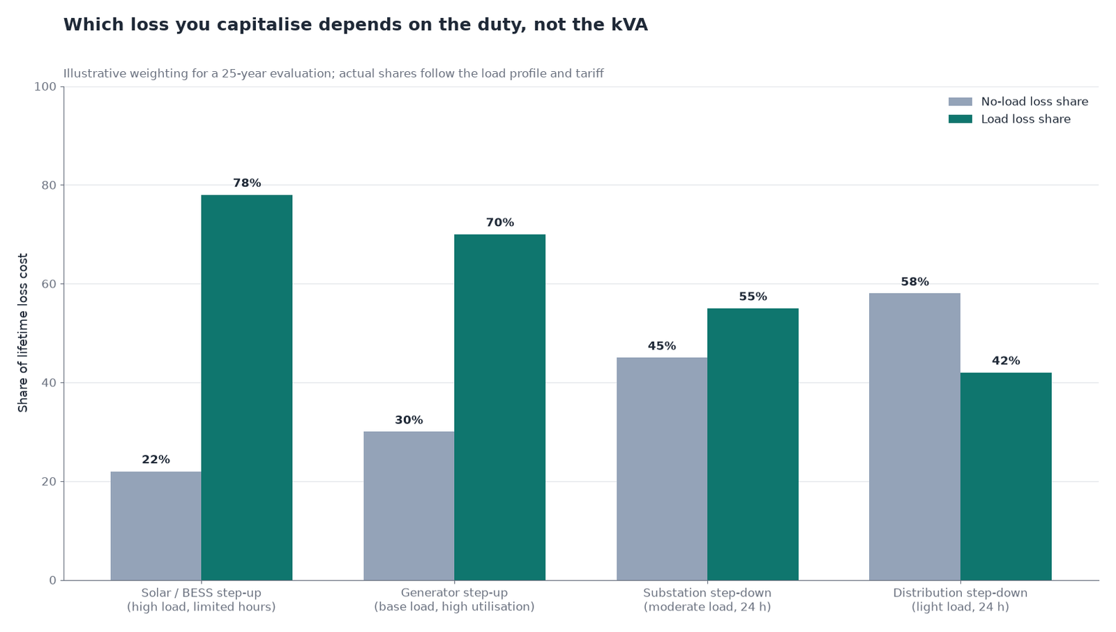
Loss evaluation is directional in practice even though the physics is not. A step-up transformer on a solar farm runs at high load for a limited number of hours and near zero at night; its no-load loss matters less than its load loss at peak. A step-down distribution transformer runs at moderate load continuously; its no-load loss matters every hour of the year. Getting the loss weighting backwards is one of the more expensive specification errors, because the purchase price difference is small and the lifetime cost difference is not.
The capitalisation method — converting watts of no-load and load loss into a present-value adder — is what allows those two cases to be compared on the same quotation. The mechanics, including the annuity factor that turns watts into dollars, are set out in the guide to oil-immersed transformer cost and specification.
| Mistake | Consequence | Prevention |
|---|---|---|
| Specifying a distribution unit for a solar step-up duty | Harmonic heating, DC offset saturation, short life | Specify inverter duty and the harmonic spectrum |
| Narrow tap range on a step-up unit | Cannot track grid voltage; output outside limits | Size taps to measured network variation |
| Reusing a step-down impedance target in reverse | Downstream switchgear under-rated or over-priced | Recalculate fault level at the new source |
| Assuming a unit is bidirectional because it is a transformer | Protection misoperation after a configuration change | State bidirectional duty explicitly in the specification |
| Buying on kVA alone | Cooling, impedance and taps all wrong for the duty | Specify ratio, impedance, taps and cooling together |
| Skipping the loss evaluation | Lowest price wins, highest lifetime cost installed | Capitalise losses into the comparison |
Decide the direction first, because it sets which winding faces the network and therefore where the taps, the insulation margin and the protection sit. Then fix the voltage ratio from the measured connection voltage, size the tap range from the real variation, and choose the impedance from the fault level you want downstream. The physical units that result span a wide range — the oil-immersed distribution transformer for step-down duty at the customer end, and the 35 kV oil-immersed distribution transformer for substation-level work. If you are specifying a step-up unit for a generation project, send the inverter or generator data sheet with the enquiry — it changes the answer more than the kVA figure does.
A step-up transformer raises voltage from primary to secondary and is used at generation sources; a step-down transformer lowers voltage and is used to feed distribution networks and loads. Physically they are the same machine, but the taps, impedance, cooling and protection are specified for the direction of duty.
Electrically it will transform in either direction, but the tap range, protection settings and thermal assumptions were designed for one duty. Reversing a unit without re-checking those three items is a common cause of commissioning problems.
On the high-voltage winding, as with a step-down unit, but with a wider range because grid voltage variation across the operating band is larger than the trim needed on a distribution transformer.
Commonly 0.4/35 kV, 0.8/35 kV or 0.315/35 kV, depending on the inverter output voltage and the collection system voltage. Dual low-voltage windings are often used to combine two inverters per transformer.
Because the source has its own impedance. On a generator step-up unit the transformer impedance limits how much fault current the generator contributes to the high-voltage network, and it also affects voltage regulation, so the target is a balance rather than a default value.
Often yes. YNd11 is common for generator step-up duty, while Dyn11 is the usual choice for distribution step-down. Vector group also determines how the earth-fault protection behaves on each side.