Transformer Sizing: How to Calculate kVA for Industrial Loads
Published: Author: Lisa
Most transformer enquiries that arrive with the wrong rating do not come from bad engineering. They come from a missing step. Someone adds up the nameplate kilowatts in the switchroom, divides by 0.8, and asks for the nearest size above the answer. That number is a ceiling, not a duty — and buying to it either wastes capital or leaves the unit running hot for twenty years.
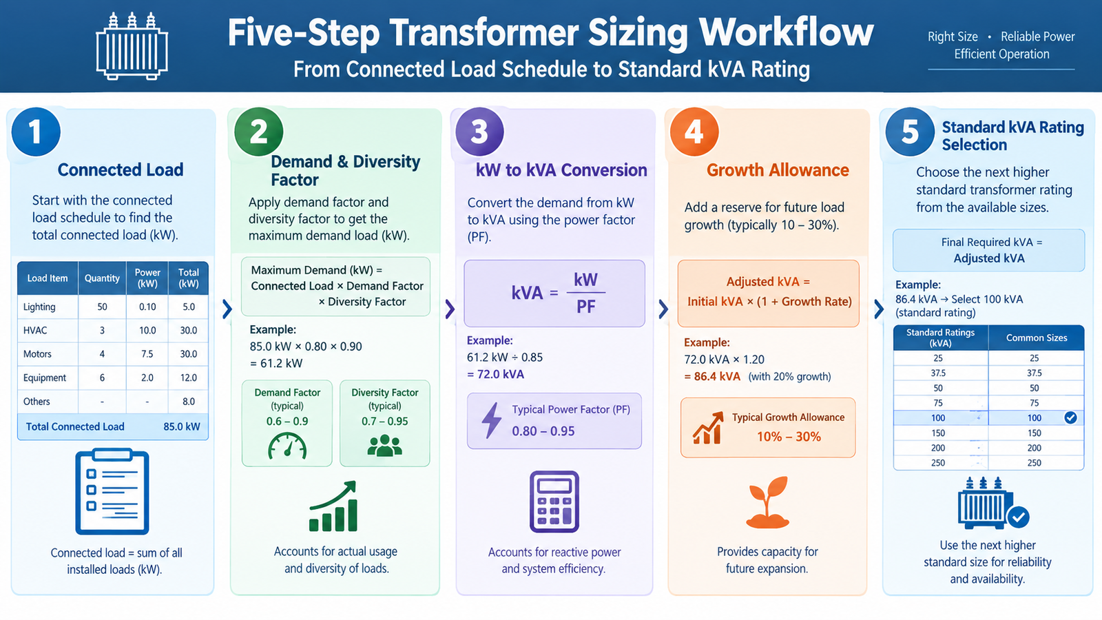
Correct transformer sizing is a five-step arithmetic chain with four engineering checks bolted on the end. The chain is easy to reproduce; the checks are what separate a rating that survives commissioning from one that trips on the first hot afternoon. This guide walks through the chain with numbers you can substitute directly, then covers the factors that quietly move the answer.
What Transformer Sizing Actually Decides
A transformer is rated in kVA, not kW, because its thermal limit is set by current. Current flows whether the load is useful work or reactive magnetising current, and the copper and insulation do not care which. That single fact drives everything that follows: you cannot size a transformer on kilowatts alone, and you cannot size it on connected load alone.
Four decisions come out of the sizing exercise, and all four carry cost:
Rated power (kVA) — the nameplate figure, chosen from the standard series.
Loading point — how hard the unit runs at normal peak. This sets losses, temperature rise and insulation life.
Unit count — one large transformer or two smaller ones, which is a redundancy and outage-cost decision as much as an electrical one.
Impedance class — because a rating comes with a standard percentage impedance, and that value sets the fault level your downstream switchgear must survive.
Step 1: Build the Connected Load Schedule
List every load the transformer will feed, with its actual operating rating rather than its nameplate. A 55 kW motor that runs at 70% of shaft rating draws roughly 38.5 kW of mechanical output, and the electrical input is that figure divided by motor efficiency. Using nameplate kW everywhere inflates the total by 15–30% before any factor is applied.
Group the schedule by behaviour rather than by location, because each group is treated differently later:
Load group
Behaviour
How it affects the rating
Continuous base load
Runs 24/7 at a steady level — servers, pumps, process lines
Sets the average loading and therefore the loss bill
Intermittent load
HVAC, machine tools, elevators, welding sets
Drives the daily peak but not the daily average
Peak impact load
Large direct-on-line motors, compressors, crushers
Sets voltage dip and starting current, not steady kVA
Non-linear load
VFDs, UPS rectifiers, LED drivers, inverters
Adds harmonic heating; may require K-rating or derating
Record power factor alongside each group. Mixed industrial plant typically sits at 0.85–0.90 before correction; motor-heavy plant with no capacitor bank can be 0.80 or lower, and a facility with modern VFDs and active front ends can reach 0.95 or better.
Step 2: Apply Demand and Diversity Factors
Two different factors are often merged into one number, which is where the arithmetic starts to drift.
Demand factor is the ratio of a load’s actual maximum demand to its connected rating — a 100 kW motor that never exceeds 70 kW has a demand factor of 0.7. Diversity factor accounts for loads not peaking together, and applies across a group rather than to an individual item.
Installation type
Typical demand factor
Notes
Residential apartment block
0.35 – 0.50
Very high diversity between flats
Office building
0.50 – 0.70
HVAC dominates and follows weather
Retail and commercial
0.60 – 0.75
Lighting plus HVAC plus escalators
Light industrial
0.60 – 0.80
Single-shift operation with idle periods
Heavy industrial, continuous process
0.80 – 0.95
Process runs close to design output
Data centre
0.85 – 1.00
IT load is designed to run near capacity
Water pumping station
0.80 – 1.00
Duty/standby pumps alternate
Use measured data from a comparable existing installation wherever it exists. The table values are starting points for a feasibility estimate, not a substitute for a load study, and a 10-percentage-point error in the demand factor moves a 1,000 kVA decision by a full standard size.
Step 3: Convert kW to kVA With the Right Power Factor
For a three-phase system the conversion is direct:
kVA = kW ÷ power factor Full-load current (A) = kVA × 1000 ÷ (√3 × line voltage)
The power factor is not a rounding detail. For a 500 kW demand, the required apparent power moves by a full 25% across the usual industrial range:
Power factor
Apparent power for 500 kW
Typical situation
0.80
625 kVA
Motor-heavy plant, no correction
0.85
588 kVA
Mixed industrial, partial correction
0.90
556 kVA
Industrial with capacitor banks
0.95
526 kVA
Modern plant, active front ends
1.00
500 kVA
Resistive or fully compensated — rare
If power factor correction is planned, size on the corrected figure only after confirming the capacitor bank will be commissioned before the full load is connected. Sizing on a power factor the site does not yet achieve is a common cause of overloaded units in the first year.
Step 4: Add Growth Margin and Set a Loading Target
Two allowances belong here, and they are not interchangeable.
Growth margin is a forecast of load you expect to add: a second production line, EV chargers, a new wing. Where a phase two is already designed, use its actual figure. Where nothing is planned, 15–25% is conventional — but treat it as a judgement. Adding 25% to a load that genuinely will not grow means paying for no-load losses on unused capacity for the next 25 years.
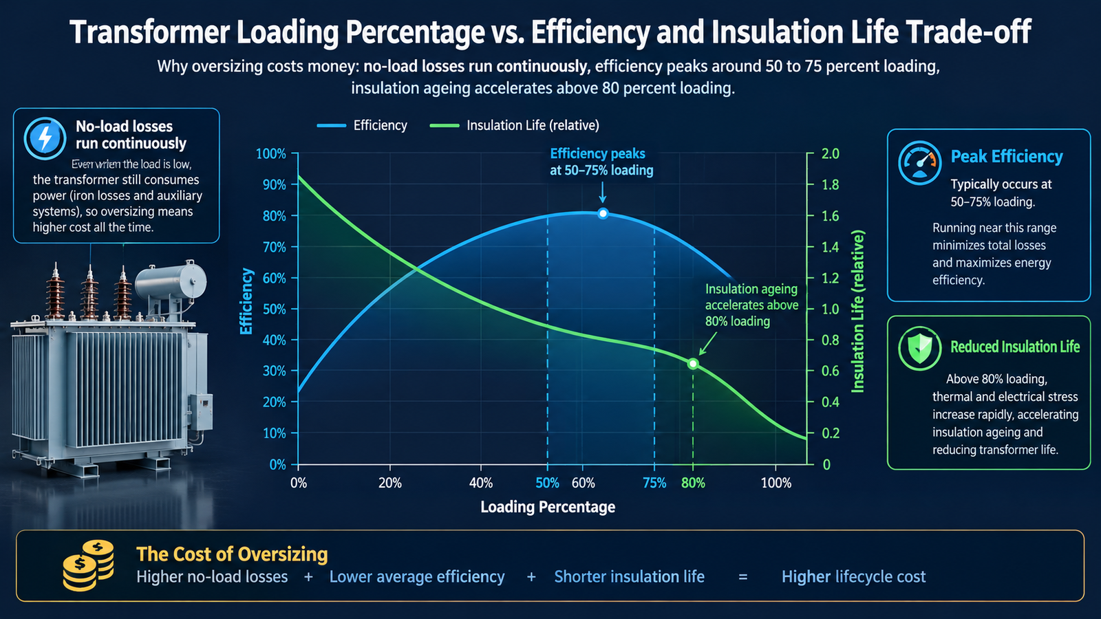
Loading target is different: it is the percentage of rated kVA you intend to run at under normal peak. A transformer is thermally happiest between 50% and 80% loading. Below about 40% the no-load loss dominates and the unit is inefficient for its whole life; above about 85% continuously, insulation ageing accelerates sharply and any overload event has nowhere to go.
Combining the two gives the design capacity:
Design kVA = maximum demand kVA × (1 + growth margin) ÷ loading target
A 325 kVA office demand with 20% growth and a 75% loading target gives 325 × 1.20 ÷ 0.75 ≈ 520 kVA, which lands on a 630 kVA standard unit once you allow for the temperature correction discussed below.
Step 5: Select the Next Standard kVA Rating
Transformers are built in a preferred series. Never specify a calculated number; select the next standard rating above the design capacity.
Series
Standard ratings (kVA)
Typical use
Small distribution
25, 50, 75, 100, 160, 200
Buildings, small plant, pole-mounted
Medium distribution
250, 315, 400, 500, 630, 800
Commercial and light industrial
Large distribution
1,000, 1,250, 1,600, 2,000, 2,500
Plant substations, data halls, renewables
Power transformer
3,150, 4,000, 5,000, 6,300, 10,000 and above
Sub-transmission, generator step-up
The electrical characteristics that come with each rating — loss figures, impedance, dimensions, weight and clearance — are fixed by design, so confirm them before finalising the room. The dry-type transformer specification reference lists these per size, and the dimension and clearance chart covers the installation footprint for 30–2,500 kVA units.
Worked Example: Two Answers for the Same Plant
A metal fabrication plant lists 1,240 kW of connected load, power factor 0.84, single-shift operation, with a 200 kW expansion planned in three years.
Step
Calculation
Result
Connected load
Given
1,240 kW
Demand and diversity
1,240 × 0.72
893 kW maximum demand
Convert to apparent power
893 ÷ 0.84
1,063 kVA
Add planned expansion
(893 + 200) ÷ 0.84
1,301 kVA
Apply 75% loading target
1,301 ÷ 0.75
1,735 kVA
Select standard rating
Next size above
2,000 kVA
If the plant had specified on connected load alone — 1,240 ÷ 0.84 = 1,476 kVA — it would have bought a 1,600 kVA unit that runs at 66% of its design duty today and is overloaded the moment the expansion is connected. The 2,000 kVA choice costs more up front and is the cheaper decision over 25 years.
Four Checks That Change the Answer After the Arithmetic
Ambient temperature and altitude
Ratings are quoted for a maximum ambient of 40 °C, a daily average of 30 °C and a yearly average of 20 °C, at altitudes up to 1,000 m. A unit in an enclosed substation room in a Gulf summer, or on a site at 2,000 m, cannot deliver its nameplate kVA. Either derate the unit or improve the room — and state which you have assumed in the enquiry, because the manufacturer will quote to the nameplate otherwise.
Harmonics from non-linear loads
VFDs, UPS rectifiers, LED drivers and solar inverters inject harmonic currents that cause extra winding and core heating a standard unit was not designed for. Above roughly 15% total harmonic distortion at the winding, specify a K-rated or inverter-duty design rather than simply buying the next size up. Oversizing does not remove harmonic heating; it only moves the operating point.
Motor starting and voltage dip
The largest direct-on-line motor draws six to eight times full-load current while starting. If that motor is a significant fraction of the transformer rating, check the voltage dip at the motor terminals — typically 15% maximum for a single start — instead of only the steady-state kVA. In some cases a larger transformer is the fix; in others a soft starter or star-delta arrangement is cheaper and better.
Short-circuit level and impedance
Every rating carries a standard percentage impedance, and fault current at the secondary terminals is inversely proportional to it. A 1,000 kVA unit at 6% impedance delivers roughly 16.7 times rated current into a bolted fault; the same unit at 4% delivers 25 times. That difference sets the breaking capacity of every breaker downstream, so the impedance decision has to be made before the LV switchgear is ordered, not after.
The Cost of Getting It Wrong in Each Direction
Symptom
Undersized unit
Oversized unit
Operating temperature
Runs at or above rated rise; hotspot ages insulation fast
Runs cool, but no-load loss is paid continuously
Efficiency point
Peak efficiency is above the actual duty, so losses rise
Operates at 25–40% load, below the efficient band
Expansion headroom
None — the next load forces a second unit
Available, but paid for years in advance
Capital cost
Lowest
Highest, plus larger room, cable and switchgear
Typical service life
Shortened, sometimes dramatically
Full life, but at a higher lifetime energy cost
The failure mode people underestimate is light loading. A transformer bought at twice the required kVA looks safe, yet its core losses run 8,760 hours a year regardless. On a 1,000 kVA unit with 1.5 kW of no-load loss, running at 35% load instead of 70% adds roughly 13 MWh of wasted energy annually compared with what the right-sized unit would consume — before any consideration of the extra capital.
One Transformer or Two?
Above roughly 1,000 kVA, splitting the load across two units is often the better answer even when one unit would be cheaper to buy:
Maintenance without downtime — a single unit means a full outage for any intervention; two units on a bus tie allow one to be isolated.
N+1 for critical loads — data halls, hospitals and process lines that cannot stop need a spare path, and that requirement usually dictates the configuration before the kVA calculation does.
Better part-load efficiency — two units running at 55% each can be more efficient than one at 110% or one at 30%.
Lower initial short-circuit level — smaller units contribute less fault current, which can reduce switchgear cost.
For a data centre specifically, the redundancy model usually sets the unit count and the load calculation only confirms it. The data centre transformer guide covers how 2N and N+1 arrangements change the sizing arithmetic.
What to Send a Manufacturer for an Accurate Quote
Sizing decisions become a quotation only when the manufacturer has enough information to select a design. A complete enquiry contains:
Maximum demand in kVA, with the demand factor and power factor you used
Primary and secondary voltages, and the tap range required by the local utility
Vector group, or confirmation that Dyn11 is acceptable
Largest single motor rating and its starting method
Share of non-linear load, or measured THD if available
Indoor or outdoor installation, ambient maximum, altitude, and whether the room is ventilated
Efficiency class or loss caps the tender requires
Required impedance, if the utility or the LV switchgear sets one
Eight lines of data remove the guesswork that otherwise becomes a change order. If you are still choosing between an oil-immersed and a dry-type design at this stage, the insulation system comparison and the dry-type selection walkthrough cover the trade-offs before the rating is fixed. Once the rating is set, confirm how it will be read on delivery against the nameplate and ratings reference, and budget against the cost per kVA benchmarks for the voltage class you need.
Conclusion
Transformer sizing is five steps and four checks. Build the load schedule on operating ratings rather than nameplates, apply demand and diversity honestly, convert with the power factor the site actually achieves, add only the growth you can justify, and divide by a loading target you are willing to defend. Then correct for ambient, harmonics, motor starting and fault level before the rating is frozen.
If you would rather have the calculation reviewed against a real design, send the load schedule and the eight parameters above — the engineering team can come back with a rating and the assumptions behind it, including the case where the honest answer is a smaller unit than you asked for.
Frequently Asked Questions
What size transformer do I need for a 500 kW load?
Divide 500 kW by the site power factor. At 0.85 that is 588 kVA, and with a 20% growth allowance and a 75% loading target the design capacity becomes about 940 kVA — so a 1,000 kVA unit. Without growth and at a 90% loading target the same load fits a 630 kVA unit. The load alone never determines the rating; the assumptions around it do.
How much spare capacity should a transformer have?
Two separate allowances. Growth margin of 15–25% covers load you expect to add, and should be reduced where no expansion is planned. Loading headroom is expressed as a target loading of 50–80% of rated kVA at normal peak. Most projects end up with 20–30% total headroom, which is enough for load swings without paying for capacity that is never used.
Is it better to oversize a transformer?
Usually not. An oversized unit runs below its efficient band, and its no-load loss is paid 8,760 hours a year for the whole service life. Oversizing is justified when a documented expansion is coming within a few years, when the load is highly cyclic, or when ambient conditions make an apparently adequate unit marginal. Outside those cases it is cheaper to buy the right size and add a second unit later.
How do I size a transformer for a large motor?
Size for the steady-state running load plus the starting voltage dip, not for the starting current multiplied by the rating. Check the dip at the motor terminals during a direct-on-line start — typically limited to 15% — and confirm the motor accelerates within its permitted time. Where the dip is excessive, a soft starter, star-delta starter or a dedicated motor transformer is usually cheaper than enlarging the main unit.
Can a transformer run above its rated kVA?
Yes, within limits, and the limits depend on the cooling class and insulation system. Dry-type units with 80 K temperature rise are commonly rated for 130% continuous loading; oil-immersed units with 55 K rise allow roughly 112%. Fans add a documented increment when running. Emergency overload beyond these figures is covered by cycling guides such as IEC 60076-7 and should be a defined operating procedure rather than an assumption in the sizing calculation.
How percentage impedance sets the fault level, the voltage drop and the parallel operating rules, with worked fault-current and regulation calculations.
Transformer ODM and OEM programs explained: the custom engineering workflow from RFQ to FAT, the 15-field spec sheet, tooling and IP ownership, MOQ and lead-time terms.