10kV vs 11kV vs 13.8kV: Choosing the Right Voltage Class
Published: Author: Lisa
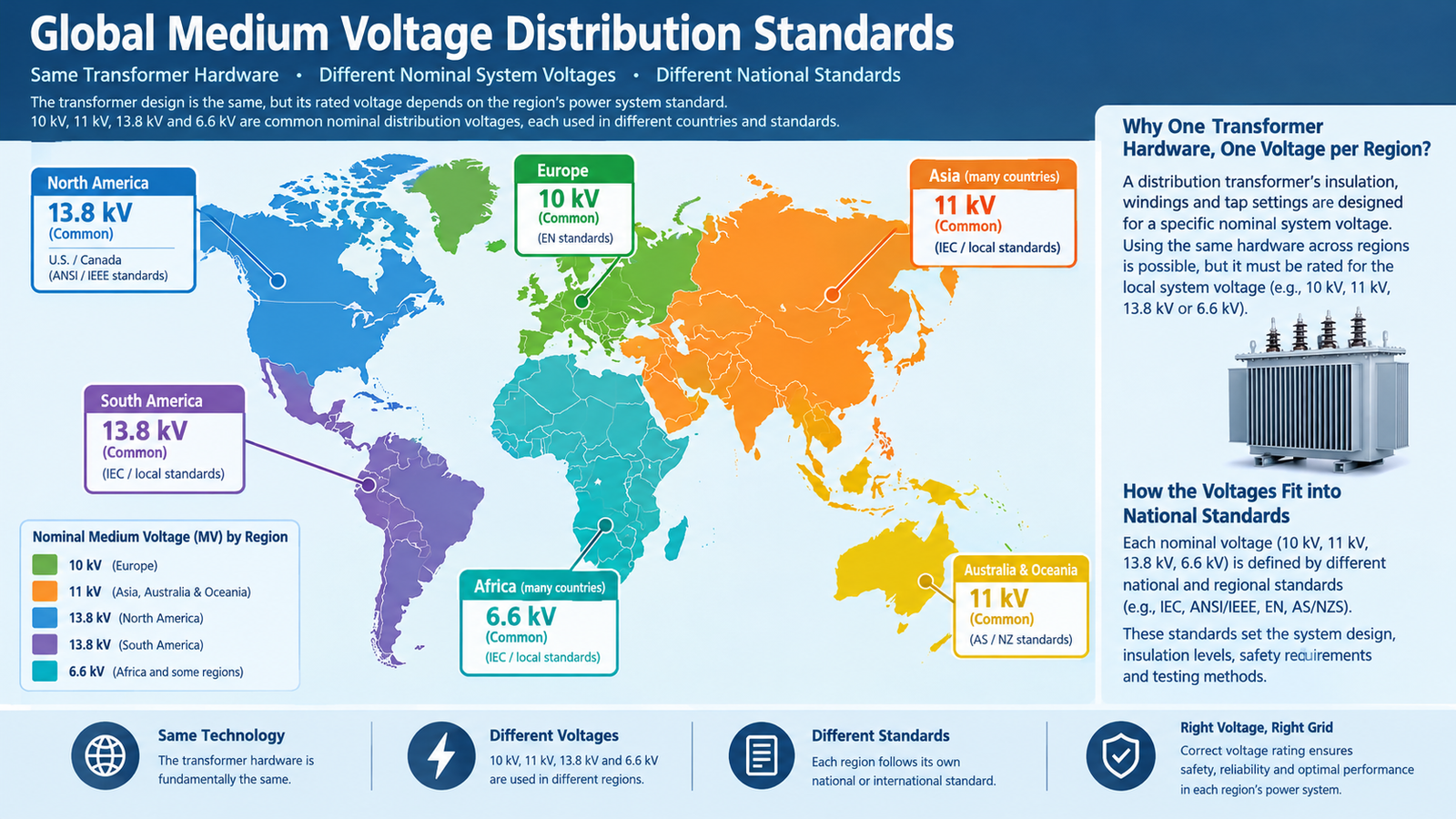
Choosing between a 10 kV, 11 kV, and 13.8 kV transformer is not a preference question. The voltage class is declared by the network you are connecting to, and the transformer has to match it in three separate ways: the nominal voltage ratio, the insulation level, and the tap range. Get the nominal right and the insulation wrong and you have a unit that reads correctly on paper and fails its impulse test in service.
The brief answer: order the class your utility declares at the point of connection, specify equipment for the next Um step above that nominal, and centre the tap range on the measured voltage rather than the nominal. 10 kV and 11 kV share the same 12 kV equipment class, so they are closer than they look; 13.8 kV does not, because it needs 15 kV or 17.5 kV class insulation and a higher basic impulse level.
Nominal voltage is not equipment voltage
Every medium-voltage system has two numbers that are easy to confuse. The nominal system voltage is what the utility calls the network — 10 kV, 11 kV, 13.8 kV. The highest voltage for equipment, written Um, is the ceiling the hardware must survive continuously, and it is always one standard step higher.
Nominal system voltage
Um (highest voltage for equipment)
Typical LV side
Common regions
6.6 kV
7.2 kV
400 V
Legacy industrial networks, parts of Asia
10 kV
12 kV
400 V / 380 V
China, parts of Europe and Africa
11 kV
12 kV
415 V / 400 V
UK, India, Middle East, Australia, Africa
13.8 kV
15 kV (17.5 kV in IEC terms)
480 V / 4.16 kV
North America, some Gulf and Latin American projects
20 kV / 22 kV
24 kV
400 V
Indonesia, parts of Europe and Asia
33 kV / 35 kV
36 kV
11 kV / 10 kV
Sub-transmission in most 50 Hz markets
Regions overlap and utilities change practice, so treat the last column as orientation and the utility’s written declaration as fact. The distinction that matters commercially is this: 10 kV and 11 kV both sit under the same 12 kV Um, which is why one transformer design can often serve both. A 13.8 kV system sits under 15 kV class equipment and cannot be served by a 12 kV design, whatever the tap range says.
Insulation level is where 13.8 kV separates
Insulation coordination is governed by the basic impulse level (BIL) and the power-frequency withstand. These are the numbers that decide whether the winding survives a switching surge or a lightning impulse, and they are not interchangeable between classes.
Um
Lightning impulse withstand (kV peak)
Power-frequency withstand (kV rms)
Used for nominal
7.2 kV
60
20
6.6 kV
12 kV
75
28
10 kV, 11 kV
17.5 kV
95
38
13.8 kV, 15 kV
24 kV
125
50
20 kV, 22 kV
36 kV
170
70
33 kV, 35 kV
Look at the 12 kV row and the 17.5 kV row together. A transformer built for 11 kV has 75 kV BIL; a 13.8 kV system typically specifies at least 95 kV, and North American practice often asks for 110 kV. That 20 to 35 kV gap is not a margin you can absorb by turning a tap. It is a different winding insulation design, a different lead clearance, and often a different bushing.
10 kV and 11 kV: closer than the names suggest
Because both sit under 12 kV Um, a 10 kV transformer and an 11 kV transformer are usually the same insulation system with a different turns ratio and a different tap range. That is why 10 kV units are frequently offered into 11 kV projects and vice versa. Whether the substitution is legitimate depends entirely on the tap range and the declared voltage ratio.
10 kV design on an 11 kV system. A ±2×2.5 percent tap range centred on 10 kV reaches 10.5 kV at the top tap — short of 11 kV. The unit will run permanently over-excited, with high no-load current and elevated temperature. Either re-tap the winding around 11 kV or specify a wider range.
11 kV design on a 10 kV system. Usually workable, because the taps can be set to reduce the ratio. Confirm the tap can reach 10 kV with the winding as designed.
LV side mismatch. A 10 kV/400 V unit and an 11 kV/415 V unit have almost the same turns ratio. Mixing a 400 V secondary into a 415 V network, or the reverse, shifts every downstream voltage by nearly 4 percent.
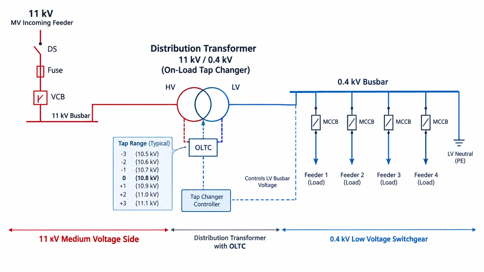
If the tap logic is unfamiliar, the difference between an off-circuit changer and a regulating one is explained in the tap changer comparison guide.
Centre the tap range on the measured voltage
The most common specification error in export orders is centring the taps on the nominal instead of the measured voltage. Utilities routinely run a few percent above nominal at the substation to compensate for feeder drop, so the transformer at the far end sees something different from the nameplate.
Take an 11 kV system where logging shows 11.3 kV at the connection point all day. A ±2×2.5 percent range centred on 11 kV covers 10.45 to 11.55 kV, so the unit sits about one tap above nominal — acceptable but with no headroom for a rise. Centring the winding on 11.3 kV puts nominal operation at the middle tap and leaves margin in both directions. The difference in cost is negligible; the difference in operating temperature is not.
Frequency is the hidden trap
Core flux is proportional to voltage divided by frequency. That single relationship explains why a transformer cannot simply be relabelled between 50 Hz and 60 Hz markets.
A 50 Hz design on a 60 Hz system at the same voltage: flux falls by about 17 percent, so the core runs cooler and quieter. Usually acceptable, though impedance and losses shift slightly.
A 60 Hz design on a 50 Hz system at the same voltage: flux rises by 20 percent, pushing the core toward saturation. Excitation current climbs sharply, no-load loss and noise rise, and the winding runs hot. This is a common and expensive mistake when surplus North American units are redeployed.
Always state the frequency on the enquiry. “50/60 Hz” is not a specification; it means the factory will optimise for one and you will accept the consequences on the other.
The low-voltage side decides as much as the high-voltage side
Buyers focus on the primary class and then accept whatever LV voltage the factory defaults to. In practice the LV value determines whether the downstream switchgear, motors, and protection settings work.
LV nominal
Where it is standard
Note
380 V
China (legacy), some 50 Hz markets
Being replaced by 400 V in new work
400 V
IEC default across most of Asia, Europe, Africa
Most common export value
415 V
UK, India, Australia, parts of Africa
Pairs with 11 kV primary in practice
440 V
Some industrial and marine systems
Usually a plant standard, not a utility one
480 V
North America, Gulf commercial projects
Pairs with 13.8 kV primary
The difference between 400 V and 415 V is under 4 percent, which sounds trivial until a motor starter at the end of a long cable is already at its minimum acceptable voltage. Specify the LV value from the switchgear schedule, not from habit.
What happens when the class is wrong
The failure modes are predictable, and they escalate with time rather than appearing immediately.
Sustained over-excitation. An 11 kV winding on a 13.8 kV system sees 25 percent overvoltage. The core saturates, excitation current rises disproportionately, no-load loss climbs, and the unit overheats even at part load.
Inadequate impulse strength. A 75 kV BIL winding on a network specified at 95 kV or 110 kV will eventually fail at a surge it was never designed for, usually during the first storm season.
Protection mis-coordination. A different voltage ratio changes the fault current seen by relays, and settings derived for one class are wrong for the other.
Warranty exposure. Manufacturers warrant the declared operating conditions. A unit run outside its voltage class gives the factory a defensible reason to decline a claim.
The remediation is never cheap: rewind, replace, or add an upstream regulating transformer. On a 1,000 kVA unit, the cost of correcting a class error exceeds the original purchase price, and the schedule impact usually exceeds it again.
Ordering checklist for a medium-voltage transformer
Nominal system voltage at the point of connection, confirmed in writing by the utility.
Um and BIL required by the project specification, not inferred from the nominal.
Measured voltage range at the site, with the tap range centred on it.
LV nominal from the switchgear schedule, plus the vector group.
Frequency, stated once and never as a range.
Impedance that keeps the downstream fault level within breaker ratings.
Governing standard — IEC 60076, GB 1094, or IEEE C57 — and the test regime that follows from it.
Copying a neighbouring project’s voltage class. Utilities change; a 10 kV line upgraded to 11 kV leaves a trail of mismatched transformers.
Treating 10 kV and 13.8 kV as “close enough”. They are 38 percent apart in voltage and two steps apart in Um.
Ignoring BIL in the enquiry. A quote without BIL is a quote for an unknown insulation level.
Assuming a tap changer fixes a wrong ratio. Taps cover a few percent, not tens of percent.
Forgetting the frequency. A 60 Hz unit on a 50 Hz network saturates, and the seller’s datasheet will not mention it.
Conclusion
Choose the class from the network, choose the insulation from the specification, and choose the tap range from the measured voltage. Those are three different decisions, and collapsing them into one “what voltage do you need” question is how mismatches reach site. 10 kV and 11 kV are interchangeable in insulation terms but not in ratio; 13.8 kV is a different class entirely.
If you can send the utility’s declared voltage, the BIL requirement, and a week of voltage logging, the Kampa engineering team will confirm the class and tap range before the winding is released. The values that must appear on the delivered nameplate are listed in the nameplate guide, and insulation class versus temperature rise is covered in the insulation class guide.
FAQ
Can I use a 10 kV transformer on an 11 kV system?
Often yes, because both sit under 12 kV equipment class. The limit is the tap range: ±2×2.5 percent centred on 10 kV reaches only 10.5 kV, so the winding must be re-tapped around 11 kV or given a wider range.
What is the difference between 11 kV and 13.8 kV transformers?
Ratio and insulation level, not just ratio. 11 kV sits under 12 kV Um with 75 kV BIL; 13.8 kV normally requires 15 kV or 17.5 kV class equipment with 95 kV BIL or higher, and in North America often 110 kV.
Is 13.8 kV always 60 Hz?
Almost always, because it is a North American utility voltage and those networks run at 60 Hz. Confirm from the project documents rather than assuming, especially on Gulf and Latin American projects where 50 Hz equipment is sometimes specified.
Why is the equipment voltage higher than the nominal voltage?
Because networks run above nominal in practice and must tolerate transients. Um gives the hardware a continuous voltage ceiling one standard step above nominal, which is why an 11 kV system uses 12 kV class equipment.
Does a higher voltage class transformer cost more?
At the same kVA, the cost difference between 11 kV and 13.8 kV is modest. The real cost is in correcting a wrong choice: rewinding, replacing, or adding a regulating transformer, plus the schedule delay.
How to choose between VS1 indoor, ZW32 pole-mounted and ZW7 40.5 kV outdoor vacuum circuit breakers, including type codes and breaking capacity sizing.
A field-by-field walkthrough of the dry type transformer technical data sheet, including the eight fields that move the price and the errors that cause disputes.