A transformer tap changer is the part of the design that decides whether your secondary voltage stays usable when the primary voltage does not. Most medium-voltage distribution transformers are ordered with one of two arrangements: an off-circuit tap changer that you set once with the unit isolated, or an on-load tap changer that moves while the transformer carries current. The difference is not a small accessory choice — it changes the price, the footprint, the maintenance plan, and how the transformer behaves on a weak or heavily loaded feeder.
Short answer before the detail: choose a de-energized (off-circuit) tap changer when the supply voltage is stable and the tap is only there to match site conditions at commissioning. Choose an on-load tap changer when the incoming voltage swings through the day, when the transformer feeds a feeder with variable load and a tight voltage band, or when the load cannot be interrupted for a tap change. Everything else in this guide is how to specify that decision so the factory builds the right unit.
What a tap changer physically does
A tap changer selects how many turns of the high-voltage winding are in circuit. Fewer HV turns means a lower turns ratio means a higher secondary voltage. That is the whole mechanism, and it explains why a tap changer is normally fitted on the HV winding: the current there is lower, so the contacts are smaller and the insulation coordination is easier.
The relationship is inverse and roughly linear per step. If the HV winding is tapped down by 5 percent, the secondary voltage rises by about 5.26 percent, because 1 / 0.95 = 1.0526. Engineers who expect exactly 5 percent are the ones who end up with a secondary that sits slightly outside the band they promised the client.
Tap position on a 11 kV / 0.4 kV unit
HV voltage at that tap
No-load secondary voltage
Change vs nominal
+2 (adds HV turns)
11,550 V
381 V
-4.8%
+1
11,275 V
390 V
-2.4%
0 (nominal)
11,000 V
400 V
0%
-1
10,725 V
410 V
+2.5%
-2 (removes HV turns)
10,450 V
421 V
+5.3%
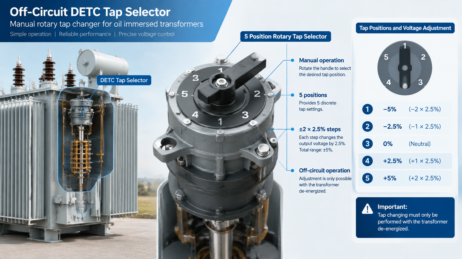
Two consequences follow from that table. First, a five-position ±2×2.5 percent tap changer covers roughly ±5 percent of supply variation. Second, the step size is a voltage decision, not a mechanical one — on a 400 V secondary, one 2.5 percent step is about 10 V, which is already a measurable share of a ±10 percent statutory band.
Off-circuit tap changer (DETC): set once, then forget
An off-circuit tap changer — also written DETC, de-energized tap changer, or manual tap changer — is a rotary selector inside the tank, operated by a handwheel or a removable handle through the tank cover. Its normal range is five positions at ±2×2.5 percent, and sometimes three positions at ±2.5 percent on small distribution units. It has no breaking capacity because it is never asked to break current: the transformer must be de-energized, isolated, and locked out before the handle is turned.
What you get for the lower cost is a part with almost nothing to wear out. There is no diverter switch, no motor drive, no separate oil compartment, no control cabinet, and no maintenance interval beyond verifying the position at commissioning and after any reconfiguration. On a 400 kVA pole-mounted or pad-mounted distribution transformer feeding a residential area, that is usually the correct engineering answer, because the supply voltage is set by the utility and the load profile does not justify continuous regulation.
What you give up is speed and range. A DETC cannot follow a daily voltage curve, and it cannot be adjusted without an outage. If the feeder is the end of a long rural line where voltage sags at evening peak, a five-position off-circuit changer will only move the problem, not solve it.
When a DETC is the right call
The transformer is on a utility feeder with a regulated voltage and the tap is set at commissioning.
The site voltage differs from nameplate by a fixed amount that is known before delivery.
Outages are acceptable and the operations team can perform a tap change under a planned isolation.
Capital cost and simplicity dominate, as on standard distribution units and most OEM private-label builds.
On-load tap changer (OLTC): regulation while energized
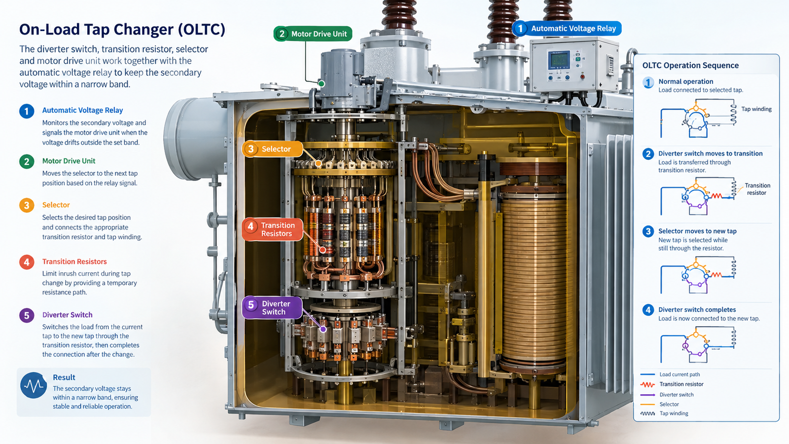
An on-load tap changer changes taps while the transformer carries load, without interrupting the supply. It does that by temporarily inserting an impedance between the two taps it is bridging, so the current never sees an open circuit. The assembly has three working parts: a selector that picks the tap, a diverter switch that makes and breaks under current, and a motor drive unit that sequences the operation and reports position.
Typical ranges are ±8×1.25 percent (±10 percent in 16 steps) on distribution and small power transformers, and ±9×1.667 percent or wider on larger units, giving 17 or 19 positions. A step takes a few seconds, and the automatic voltage relay — often called an RTCC or AVR — decides when to move based on a measured secondary voltage, a deadband, and a time delay so the changer does not hunt on short transients.
The reason OLTCs are common on transmission and sub-transmission transformers and much rarer on 400 V distribution units is economic. An OLTC adds a diverter switch with wearing contacts, a separate oil compartment that needs its own oil testing, a motor drive, a controller, and typically 15 to 30 percent to the transformer price. On a 30 MVA unit that is a rounding error against the cost of poor voltage. On a 630 kVA unit it can exceed the value of the losses it saves.
Resistor type and reactor type
Two transition principles dominate. The resistor type inserts transition resistors for a few tens of milliseconds, makes and breaks quickly, and is the standard choice in IEC markets for medium and high voltage. The reactor type uses a preventive autotransformer or reactor to limit circulating current, breaks in oil, and remains common in North American practice. Both work; they differ in maintenance routine, oil quality sensitivity, and the spare parts your local service partner is likely to stock.
A newer variant replaces the oil-immersed diverter contacts with vacuum interrupters. The switching duty then happens in a sealed bottle rather than in oil, so the OLTC compartment oil stays clean far longer and the maintenance interval stretches. It costs more up front and is worth asking about on units where a tap change happens many times a day, such as a transformer feeding a steel mill, a traction rectifier, or a data center with a volatile upstream voltage.
DETC versus OLTC at a glance
Parameter
Off-circuit (DETC)
On-load (OLTC)
Operation
Only with transformer de-energized
Under full load, no interruption
Typical range
±2×2.5% (5 positions)
±8×1.25% to ±9×1.667% (17–19 positions)
Step size
2.5%
1.25% or 1.667%
Wearing parts
Selector contacts only
Diverter contacts, motor drive, controller
Oil management
Single tank
Separate OLTC compartment, own oil tests
Maintenance
Inspection at commissioning, then as-found
Contact inspection and oil change on operation count
Controls needed
None
Motor drive, RTCC/AVR, position indication, alarms
Cost impact
Baseline
Typically +15% to +30% on the transformer
Best fit
Stable utility supply, distribution units
Variable supply, tight voltage band, critical load
How to choose for a real project
Work from the measured voltage, not from the nominal. Ask the utility or the site electrical team for a week of primary voltage logging at the connection point, and note the maximum, minimum, and the daily pattern. Then apply the decision table below.
Site condition
Recommended
Reason
Primary within ±3% of nominal all day
DETC, 5 positions
Taps only compensate a fixed offset
Primary swings ±5% to ±10% daily
OLTC, ±8×1.25%
Needs 16 steps and automatic control
Long rural feeder, evening sag
OLTC plus line-drop compensation
Voltage drop is load-dependent
Transformer feeds a rectifier or arc load
OLTC, vacuum diverter preferred
High tap-change count wears oil contacts
Parallel transformers on one busbar
OLTC on both, master-follower control
Mismatched taps circulate current
Pad-mounted unit, no control power
DETC
No auxiliary supply for a motor drive
If the answer is OLTC, also confirm that control power, a current transformer for line-drop compensation, and a place to mount the controller actually exist in the substation. An OLTC delivered without a working AVR is an expensive manual tap changer.
Specifying tap range without getting it wrong
State four things on the datasheet and the factory cannot misread you: the tap range as a percentage, the number of steps, the voltage at each extreme, and the winding the changer sits on. Use the real system voltage as the centre point, not the nameplate nominal of a neighbouring project.
Centre the range on the measured voltage. If the site runs at 10.7 kV against a 10 kV nominal, a ±2×2.5 percent changer centred on 10 kV reaches only 10.5 kV. The fix is a tapped winding centred on 10.7 kV, or a wider range.
Check the step in volts on the secondary. A 1.25 percent step on a 400 V secondary is 5 V. That is the resolution your AVR has to work with.
Decide the winding. HV tapping is standard; LV tapping exists on some furnace and rectifier transformers but is a specialist design.
Declare the tap position used for the guarantee values. Impedance, losses, and temperature rise should be stated at a named tap, normally the principal tapping.
The tap changer is also a routine and type test item, not just a purchase line. Sequence tests, dielectric tests across the open gap, and a full tap-cycle run belong in the factory acceptance programme, and they are covered in a proper factory acceptance test plan under IEC 60076.
Maintenance and lifecycle cost
A DETC has no maintenance interval in any meaningful sense: verify the position at commissioning, record it, and re-verify after any work on the unit. An OLTC does have one, driven by tap-change count rather than calendar time. A distribution OLTC might see a few thousand operations a year; a transformer on an unstable industrial feeder can see tens of thousands.
Track the operation counter, not the date. Maintenance is triggered by operations, and the counter is the only honest record.
Test the OLTC oil separately. Dissolved gas analysis on the diverter compartment is the earliest warning of contact wear or arcing problems, and mixing it with main-tank oil hides the signal.
Inspect contacts before they fail. Worn diverter contacts show up as increasing acetylene and a rising temperature differential, not as an alarm.
Budget the controller. RTCC relays fail more often than the mechanical changer, and a replacement programmer is a lead-time item.
When you capitalise the difference properly, the economics are clear. A 1,000 kVA distribution transformer with an OLTC might cost 20 percent more than the DETC version; that premium has to be repaid by avoided voltage complaints, avoided production loss, or avoided tap changes on a de-energized basis. On a critical process load the case is easy. On a standard commercial building it usually is not, and the DETC plus a correctly centred tap wins.
Five specification mistakes that show up at commissioning
Asking for an OLTC but no automatic controller. The transformer regulates nothing; an operator has to press buttons. Specify RTCC with the deadband and time delay you want.
Centring the tap range on the wrong voltage. Offshore projects frequently copy a 10 kV tap range onto an 11 kV system. The unit then runs permanently at one extreme.
Ignoring parallel operation. Two transformers with different tap positions on the same busbar will circulate current. Specify the control scheme, master-follower or negative reactance, at the same time as the changer.
Forgetting that the OLTC needs space and oil volume. A larger tank, a motor drive on the cover, and a cable route to the controller all change the footprint. Late changes are expensive.
Not naming the tap position for guaranteed values. Losses and impedance measured at a different tap than the one the client assumes is a classic acceptance dispute.
If you are still deciding the transformer itself, the wider selection logic — kVA, impedance, cooling, and vector group — sits in the power transformer guide, and the practical order-of-selection questions are laid out in how to select an oil-immersed transformer.
Conclusion
The tap changer question resolves to one measurement: how much does the primary voltage actually move. Stable supply, fixed offset, standard distribution duty — a five-position off-circuit changer is the honest, economical answer. Moving supply, tight voltage band, load that cannot be interrupted — specify an OLTC with a real controller, a named range, and a maintenance plan based on operation count. Get the range centred on the measured voltage and the rest of the specification follows.
If you are sizing a unit for a specific site and want the tap range checked against your voltage logs, the team at Kampa can review the datasheet against the actual feeder conditions before the winding is designed. Cost expectations by rating are covered in the oil-immersed transformer cost breakdown, and the values you should cross-check on delivery are in the nameplate ratings guide.
FAQ
What does DETC stand for on a transformer?
DETC means de-energized tap changer, also called an off-circuit tap changer. It can only be operated when the transformer is isolated and de-energized, typically with a handwheel on the tank, and normally offers five positions at ±2×2.5 percent.
Can I change a DETC tap while the transformer is energized?
No. The selector has no breaking capacity, so operating it under load causes an arc that damages contacts and can fail the winding. Isolate, lock out, change the tap, and record the new position before re-energizing.
How many tap positions does an OLTC usually have?
Most medium-voltage on-load tap changers have 17 or 19 positions, typically ±8×1.25 percent or ±9×1.667 percent, giving a regulation range of about ±10 percent in 16 or 18 steps.
Why is the tap changer fitted on the high-voltage winding?
Because the current is lower there. Lower current means smaller contacts, less contact wear, and easier insulation coordination. The tap also produces a finer voltage resolution on the secondary when it acts on the higher turn count.
Does an OLTC increase transformer losses?
The changer itself adds negligible loss, but the extra contacts and transition impedance add a small amount. The larger practical effect is on price, footprint, and maintenance rather than on efficiency.
How often does an OLTC need maintenance?
On operation count, not calendar time. Typical practice is a first inspection after the first few thousand operations, then contact inspection and oil treatment at intervals set by the manufacturer, with dissolved gas analysis on the diverter oil monitored in between.
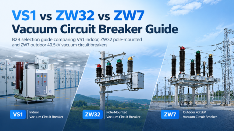
How to choose between VS1 indoor, ZW32 pole-mounted and ZW7 40.5 kV outdoor vacuum circuit breakers, including type codes and breaking capacity sizing.
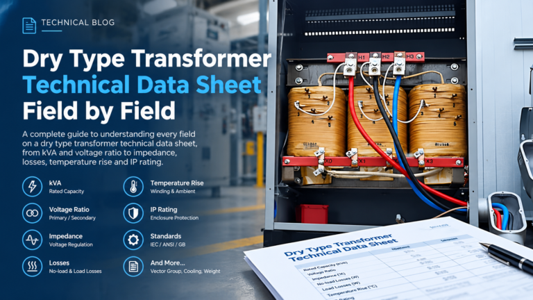
A field-by-field walkthrough of the dry type transformer technical data sheet, including the eight fields that move the price and the errors that cause disputes.