Partial Discharge in Cast Resin Transformers: Limits and Test
Published: Author: Lisa
Partial discharge is the acceptance criterion that separates a cast resin transformer built to last thirty years from one that fails in year six, and it is the one number in the test report that a buyer can check without any test equipment. For dry-type transformers to IEC 60076-11, the commonly specified limit is not more than 10 pC measured at 1.1 times the rated system voltage divided by √3. A unit that measures 3 pC and a unit that measures 90 pC can both pass a routine ratio and insulation resistance test — only the PD result tells them apart.
This guide explains what partial discharge is in a cast resin winding, where the limits come from, how the test is actually run, what the reading means at different values, and what to do when a unit misses the limit. The physical construction that determines PD performance is covered in the guide to dry-type power transformers, and specifically in the article on cast resin construction.
What Partial Discharge Is, and Why Cast Resin Is Exposed to It
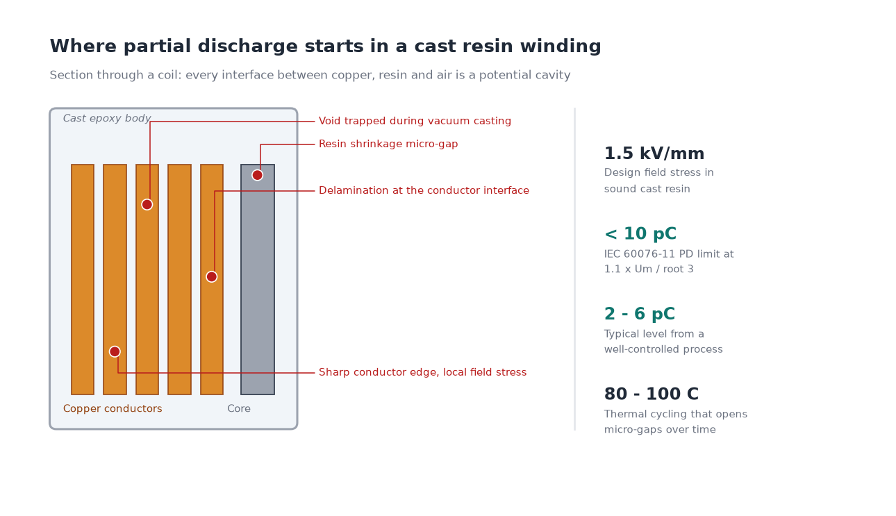
Partial discharge is a localised electrical breakdown that does not bridge the full insulation between two electrodes. It happens inside a gas-filled void, along an interface between materials, or at a sharp electrode edge, and it repeats at every half cycle. Each event erodes a few molecules of insulation and deposits decomposition products. The damage is cumulative, and the mechanism accelerates: a void that discharges grows, and a growing void discharges harder.
A cast resin winding is a composite — copper conductors, a foil or wire winding, interlayer insulation, cast epoxy with silica filler, and the interfaces between all of them. Every interface is a potential cavity. The epoxy cures with shrinkage that can pull it away from the conductor. Thermal cycling from load variation opens micro-gaps. A sharp conductor corner concentrates field stress. None of these defects shows up in a ratio test, a winding resistance measurement, or an insulation resistance reading, because the insulation is still intact — it is only partially bridged.
Oil-immersed transformers have a different exposure. The oil impregnates and fills voids, and the PD mechanism is dominated by gas bubbles generated by overheating or by moisture. That is why the limits differ: dry-type limits are set in the low tens of picocoulombs while oil-immersed acceptance limits are typically two orders of magnitude higher.
The Limits: What the Standards Actually Require
IEC 60076-11 is the reference standard for dry-type power transformers and it defines a partial discharge level that the winding must not exceed during the routine dielectric tests. The figure is 10 pC, and it is quoted at the test voltage of 1.1 × Um/√3, where Um is the highest voltage for equipment.
System voltage Um
PD test voltage (1.1 Um/√3)
Standard limit
Tightened specification
7.2 kV
4.6 kV
10 pC
5 pC
12 kV
7.6 kV
10 pC
5 pC
24 kV
15.2 kV
10 pC
5 pC
36 kV
22.9 kV
10 pC
5 pC
40.5 kV
25.7 kV
10 pC
5 pC
Two practical notes. First, the 10 pC figure is a ceiling, not a target — a well-made cast resin winding typically measures in the 2 to 6 pC range, and a supplier reporting “less than 10 pC” on every unit is reporting a pass, not a quality level. Second, the exact test sequence and any preconditioning voltage should be read from the edition of the standard named in the purchase order, because editions differ and because the buyer’s specification often adds requirements above the baseline. The surrounding test programme is described in the factory acceptance test guide.
How the Test Is Run
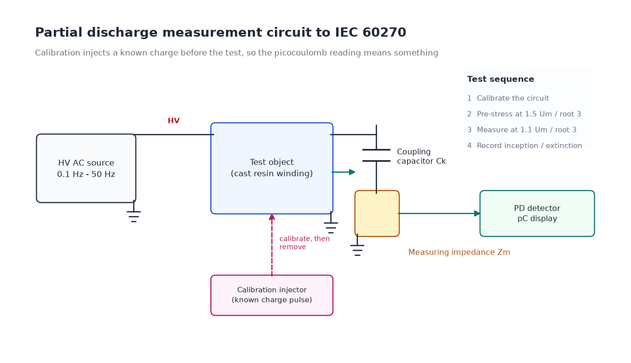
The measurement itself uses the IEC 60270 method: a coupling capacitor and a measuring impedance in the test circuit, with the discharge magnitude calibrated by injecting a known charge pulse before the test. The calibration step is what makes the picocoulomb figure meaningful; without it, the reading is just a number on a dial.
Calibrate the measuring circuit by injecting a known charge at the terminals and confirming the instrument reads it correctly, then remove the calibrator.
Raise the voltage to a pre-stress level, commonly 1.5 × Um/√3, and hold briefly. This conditions the insulation and reveals defects that only appear above operating stress.
Reduce to the measurement voltage of 1.1 × Um/√3 and hold for the defined period, recording the discharge magnitude.
Record the inception and extinction voltages where the specification requires them — PD inception voltage (PDIV) and PD extinction voltage (PDEV) describe how much margin exists, which a single magnitude figure does not.
Run the sequence on each winding separately, with the other windings earthed, so that the measurement is not contaminated by a second circuit.
The test is normally carried out alongside the induced overvoltage test and the applied voltage test, since the voltage source and the shielded room are already set up. Doing PD as a standalone test on a finished unit means shipping it back to a test bay if it fails, which is why it belongs in the routine sequence rather than the site acceptance scope.
Reading the Result
Measured level
Interpretation
Action
Under 5 pC
Clean insulation system, well impregnated, void-free interfaces
Accept; typical of good cast resin work
5 to 10 pC
Minor voids or interface activity present but within standard
Accept for general distribution duty; query if the specification is 5 pC
10 to 50 pC
Beyond the IEC limit; a real defect exists somewhere
Reject, or require investigation and retest after treatment
50 to 200 pC
Significant cavity or delamination; will propagate in service
Reject; the winding is not repairable without rework
Above 200 pC
Severe defect, possibly a crack or a contaminated interface
Reject; investigate the casting process, not just the unit
A number alone is not the whole story. A unit that measures 8 pC but whose inception voltage is barely above the operating voltage has very little margin, because any voltage rise in service will push it into sustained discharge. A unit that measures 8 pC with inception at twice operating voltage is comfortable. If the specification allows it, ask for inception and extinction voltages alongside the magnitude.
What Causes Elevated Partial Discharge
PD in a cast resin transformer almost always traces to one of six causes, and the pattern in the test data often identifies which.
Casting voids. Air or gas trapped during vacuum casting, usually in thick sections or at the junction between the winding and the lead exit. The most common single cause.
Delamination at the conductor interface. Epoxy shrinkage during cure pulls the resin away from the copper, leaving a thin gap that concentrates stress.
Sharp electrode edges. A conductor corner or a foil edge with a small radius produces local field enhancement far above design stress.
Moisture absorption. Cast resin is not hermetic. Units stored in humid conditions before testing, or with damaged surface coatings, show elevated PD that falls after drying.
Contamination during casting. Dust, release agent residue or metal particles in the resin introduce local permittivity changes and field distortion.
Mechanical damage after casting. Cracks from handling, over-tightened terminals or thermal shock open paths that discharge.
The remedy is always in the process, not the test. A supplier whose units routinely measure 20 to 40 pC has a vacuum casting or cure problem, and tightening the acceptance limit without changing the process simply moves the rejects to a later stage. This is why PD is described as a process indicator as much as a product test — the same logic that makes loss measurement an indicator of design quality, covered in the article on transformer efficiency classes and losses.
Partial Discharge Alongside the Other Quality Signals
PD does not replace the other tests, and the other tests do not replace PD. The useful picture comes from reading them together.
Test
What it catches
What it misses
Partial discharge (IEC 60270)
Voids, delamination, field enhancement
Winding geometry errors, connection mistakes
Insulation resistance / PI
Moisture, gross contamination, tracking paths
Localised defects in sound insulation
Applied voltage withstand
Gross insulation weakness that fails outright
Defects that survive the one-minute test
Induced overvoltage
Turn-to-turn and phase-to-phase weakness
Defects not stressed by the test voltage profile
Ratio and polarity
Winding errors, tap connection mistakes
Anything related to insulation quality
No-load and load loss
Core and winding design or assembly problems
Insulation defects entirely
The full specification of what a routine test report should contain, and how the values relate to the design data sheet, is set out in the guide to the dry-type transformer specification.
Partial Discharge After Installation
Factory PD says nothing about what happens after transport, and transport is where cast resin units take damage. A crack initiated by a lifting sling or a poorly blocked shipment will not appear in a visual inspection but will show as PD once energised. For critical installations — data centres, hospitals, tunnel substations — a site PD measurement before handover closes that gap.
Onsite PD measurement is harder than factory measurement because the environment is electrically noisy. Online methods use high-frequency current transformers on the earth connection, ultra-high-frequency sensors, or acoustic detection, and each trades sensitivity for practicality. A common approach is a baseline measurement at commissioning, repeated annually, so that a trend is available before a failure. Absolute values are less useful than the trend, because site conditions vary.
The insulation system that determines how much PD margin a unit has in the first place is covered in the guide to dry-type transformer insulation, including the temperature class and material choices that interact with the casting process.
Conclusion
Treat the partial discharge figure as a process signature rather than a pass mark. Ask for the measured value, not just a compliance statement; ask for the test voltage and the standard edition; and treat a consistent 8 to 9 pC reading across a whole order as a warning about casting control, not as evidence of quality. On a specification where the winding has to survive decades of thermal cycling, a few picocoulombs of margin is worth more than most of the other line items on the quotation.
Frequently Asked Questions
What is the acceptable partial discharge level for a dry-type transformer?
IEC 60076-11 sets 10 pC at 1.1 times Um/√3 as the limit for cast resin dry-type transformers. Well-controlled production typically measures 2 to 6 pC; many specifications tighten the acceptance level to 5 pC.
What is a 10 pC partial discharge limit in plain terms?
It caps the charge transferred in each individual discharge event at 10 picocoulombs — an extremely small quantity. Anything above it indicates a cavity, delamination or field concentration large enough to erode the insulation over time.
Does partial discharge always lead to failure?
Not immediately, but it is progressive. Discharge erodes insulation and generates decomposition products that increase local stress, so a unit operating above its inception voltage degrades faster than the design life assumes.
Why do oil-immersed transformers have higher PD limits?
Oil fills and impregnates voids and recovers from local breakdown, so the discharge mechanism and its consequences differ. Dry-type insulation has no self-healing medium, which is why its limits are set two orders of magnitude lower.
Can a transformer with high partial discharge be repaired?
Sometimes. Surface contamination or moisture can be removed by cleaning and drying. An internal casting void or delamination cannot be repaired without rewinding the coil, which is rarely economic.
Is partial discharge tested on every unit or only on prototypes?
It is a routine test on every dry-type unit for most specifications, not a type test. Type tests establish the design; the routine PD measurement confirms each individual winding.
Step-up and step-down oil-immersed transformers differ in taps, impedance, cooling and loss weighting. Here is how to specify each duty for generation and distribution.
Compare solid, low resistance, high resistance, resonant and ungrounded MV neutrals, and size the grounding transformer and resistor that go with each method.
Decode CT accuracy classes: metering classes 0.1 to 3.0, what the S suffix changes, how 5P10 and 10P10 differ, and why burden decides the accuracy you actually get.