The single-phase overhead transformer is the least glamorous product in a medium-voltage catalogue and the one most often ordered from a photograph. That works when the order repeats an approved utility design. It fails when the unit is going to a different network, because the two things that decide whether it can be installed at all — the protection arrangement and the secondary connection — are usually not visible in the photograph, and they are not implied by the kVA.
Most single phase oil immersed transformer orders repeat a design the utility already runs, and those are the easy ones. This page is about the other case: a single-phase oil-immersed power transformer for overhead distribution where the construction has to be specified — what the conventional and CSP versions actually contain, how the two low-voltage windings are wired, and which numbers decide the rating. It assumes the choice of a pole-mounted unit over a pad-mounted one is already made.
Where a single-phase unit fits
Single-phase distribution transformers run from small rural units up to a few hundred kVA, and the standards that cover them treat the type as its own product family rather than a cut-down three-phase unit. IEEE C57.12.20, for example, covers overhead distribution transformers across a 5 kVA to 500 kVA range, which is a fair description of where the type is actually used.
| Aspect |
Single-phase unit |
Three-phase unit |
| Typical capacity |
5 kVA to 100 kVA, up to 500 kVA |
15 kVA to 2,500 kVA |
| Primary |
One phase to neutral, one or two bushings |
Three phases, three or four bushings |
| Secondary |
120/240 V three-wire, or 120 V parallel |
208Y/120 V, 480Y/277 V, 400/230 V |
| Cost per kVA |
Higher at the same kVA |
Lower at the same kVA |
| Load balance |
Must be spread across phases by the planner |
Balanced by construction |
| Best fit |
Rural runs, scattered load, single customers |
Dense load, industrial boards, plant distribution |
The economics are simple: below roughly 50 kVA a single-phase unit is cheaper to buy, lighter to hang and simpler to protect, and the unbalance it creates is small enough to live with. Above that, three-phase units win on cost per kVA and the argument shifts to which one the network already has. The structural comparison between overhead and ground-level installation is covered in pole-mounted versus pad-mounted transformers.
Conventional or CSP: the decision that changes the order
Two single-phase units of the same kVA, same voltage and same losses can be entirely different products depending on where the protective devices sit. A conventional unit is a transformer; the protection is bought and mounted separately on the pole. A CSP — completely self-protected — unit arrives with the protection integrated.
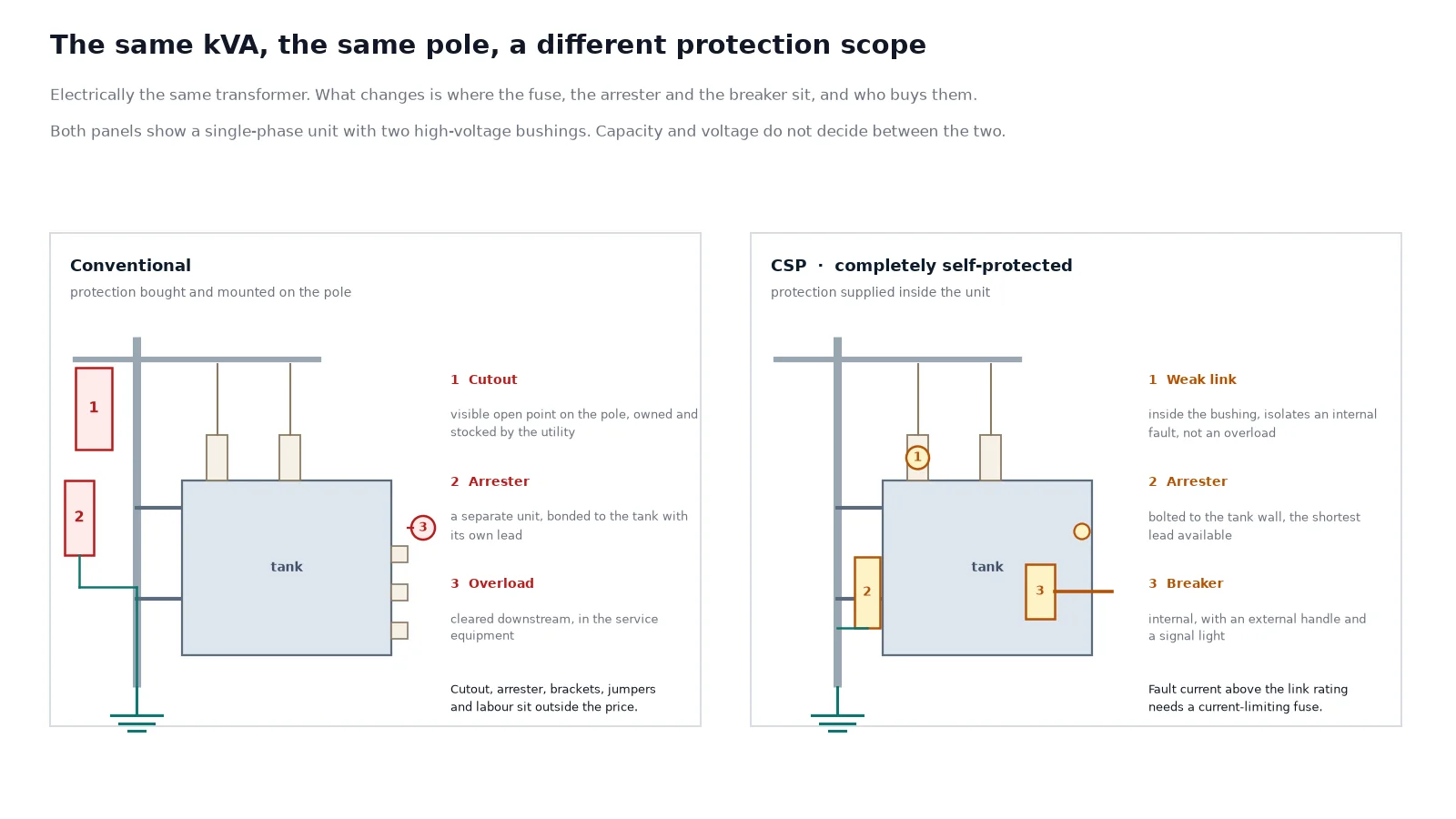
The practical consequences run in both directions, and neither construction is better in the abstract.
| Consideration |
Conventional |
CSP |
| Visible isolation point |
Yes, the cutout can be opened and seen |
No external open point; the link is internal |
| Surge arrester |
Separate, selected and stocked by the utility |
Supplied and mounted on the tank |
| Secondary overload protection |
In the service equipment downstream |
Internal breaker with an external handle |
| Pole hardware |
Cutout, arrester, brackets, jumpers, labour |
Hanger bracket only |
| Replacement fit |
Any equivalent unit fits the existing hardware |
Must match the internal device ratings |
| Spares policy |
Fuse links and arresters held as system items |
Model-specific devices recorded per unit |
| Price comparison |
Transformer price only, accessories extra |
One price, scope must be checked line by line |
The buyer’s decision is therefore not technical but procedural: which arrangement the serving utility has approved and maintains. A unit offered as CSP into a network whose standard requires an external cutout is not a cheaper installation, it is a non-compliant one, and the reverse is equally true. Ask for the protection diagram and the component schedule for the exact unit being quoted, because “CSP included” describes a category, not a bill of materials.
What a CSP unit actually contains
The name promises complete protection. What is supplied varies, so the components need to be named in the order.
- Primary weak link, mounted inside or directly behind the high-voltage bushing. Its job is to isolate a transformer that has already failed internally; it is not sized to clear a secondary overload.
- Surge arrester, bolted to the tank wall next to the high-voltage bushing. Mounting it on the tank shortens the lead, and lead length is what decides how much of a surge reaches the winding.
- Secondary breaker, inside the tank, operated by an external handle with an overload reset and usually a signal light. This is the device that responds to overload and to secondary faults.
- Current-limiting fuse, in series with the weak link, where the available fault current exceeds the link’s interrupting rating. Whether it is needed depends on the fault level at that point on the feeder, which means the utility has to state it.
Two failure modes follow from this list. The first is expecting the weak link to protect against overload; it will not, and a unit without the secondary breaker has no overload protection of its own. The second is fitting a replacement link of the wrong rating, which is why the internal device data has to be recorded against the unit serial number rather than assumed from the rating.
Voltage, taps and the high-voltage bushings
Most single-phase units are ordered with either one or two high-voltage bushings. One bushing means the primary is connected phase-to-neutral and the tank is not a primary conductor; two bushings allow the unit to be connected across two phases, which some networks use to spread single-phase load. The choice is a network decision and it changes the bushing set, the lid and often the arrester mounting.
Taps on the high-voltage winding are off-circuit and normally give plus or minus 5 % in 2.5 % steps, occasionally plus or minus 2 x 2.5 %. They trim the ratio for the actual feeder voltage; they do not change the secondary voltage class and they must be set with the unit de-energised.
Frequency is the item that catches export buyers. A unit designed for 50 Hz and operated at 60 Hz runs at lower flux density, so it is electrically safe and its no-load loss falls. The reverse is not true: a 60 Hz design placed on a 50 Hz system has its core driven closer to saturation, with overheating and a distorted secondary. State both the frequency and the standard the design is built to, and do not accept “50/60 Hz” as an answer without a design statement.
The secondary: 120/240 V, three-wire
A single-phase distribution unit carries two low-voltage windings, and the way they are linked sets what the customer can actually connect.
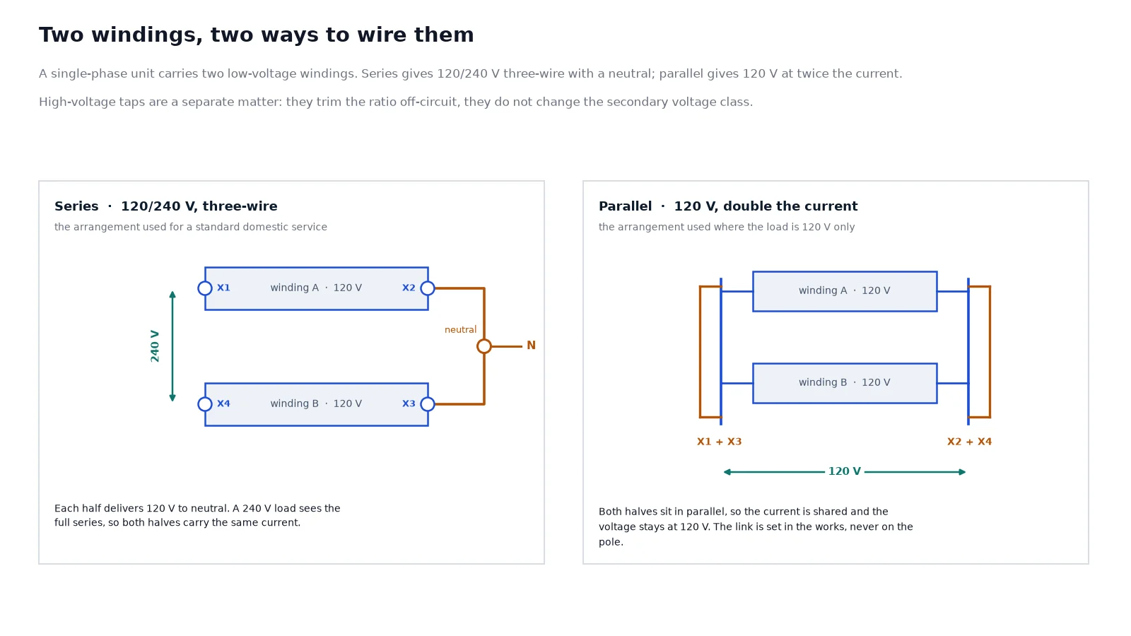
In series the two windings add, giving 240 V across the outer terminals and 120 V from either outer terminal to the midpoint, which becomes the neutral of a three-wire service. This is the standard North American arrangement and it lets one unit serve both 120 V lighting circuits and 240 V appliances. The constraint is that both halves carry the same current, so the load has to be reasonably balanced between them.
In parallel the two windings are linked side by side, giving 120 V at twice the current. This is used where the load is 120 V only and the network is not wired for three-wire service.
The link is set in the works. Re-wiring a unit on the pole to change the arrangement is not a field modification, and a unit ordered in the wrong arrangement will either deliver the wrong voltage or, if forced, put the two windings out of phase against each other. Where the secondary voltage needed by the customer differs from what the network provides, that is a job for a separate service transformer, not for a different link.
Sizing: kVA, diversity and the far end of the line
Single-phase ratings cluster on a standard ladder — 5, 10, 15, 25, 37.5, 50, 75 and 100 kVA — and sizing means picking the rung, not calculating a continuous number.
Work from coincident demand rather than connected load. A worked example: twelve rural connections with 4 kVA of connected load each, at a diversity factor of 0.6, give about 29 kVA of coincident demand, which lands on 37.5 kVA. Adding ten years of growth takes it toward 50 kVA, and the cost difference between those two rungs is small compared with a second visit from a line crew.
Two corrections are needed on top of the arithmetic.
The largest single load. A 15 kW irrigation pump starting direct-on-line will decide the rating on its own, because the voltage dip during starting is what the customer complains about, not the steady-state total.
Distance. On a long single-phase spur the voltage drop along the line, not the transformer, becomes the limit. A unit sized perfectly for the load at the pole can still leave the last customer below the minimum service voltage, and no transformer rating fixes that. This is the case where the honest answer is a larger conductor or a second unit further out.
Losses then enter the decision. Two units of the same kVA can differ by a factor of two in no-load loss depending on core material, and no-load loss runs 8,760 hours a year whether anyone is using the supply or not. The relationship between loss class, efficiency and lifetime cost is set out in transformer efficiency classes and losses.
Efficiency compliance for the destination market
Single-phase liquid-filled units are covered by minimum efficiency regulation in most markets, and the assessment point is not the same as for dry-type equipment. Under the US rule at 10 CFR 431, liquid-immersed distribution transformers are assessed at 50 % of rated load, where dry-type units in the same regulation are assessed at 35 %. A supplier quoting an efficiency figure without stating the load point has given a number that cannot be checked.
Compliance is a design choice made at order, not a label applied afterwards: it fixes the core grade, the conductor section and therefore the tank size. Amorphous metal cores are the usual route where no-load loss has to drop hard, at a higher purchase price and with a larger core frame. Where the destination is the United States or Canada, the efficiency table and the marking requirement belong in the enquiry; a unit built to a general IEC design will often not meet them.
Mounting, clearances and pole hardware
Pole-mounted installation is simple in principle and specific in practice, and the items below are the ones that stop a delivery being hung.
- Pole strength and loading. The unit weight plus the wind load on the tank is a structural load on the pole. A unit that is heavier than the pole class allows is a pole replacement, not an installation.
- Hanger bracket and spacing. The bracket has to match the tank, and the unit has to sit clear of the pole so that the high-voltage leads can be dressed without touching it.
- Ground clearance. The minimum clearance from the lowest live part to ground under maximum sag is set by the local code for the voltage class. It is a code number, not a preference, and it is measured with the conductor at its worst sag rather than at stringing tension.
- Bonding. Tank, arrester and (where used) the mounting bracket are bonded to the system neutral or to a driven earth electrode, following the utility’s practice. A single missing bond is the difference between an arrester that works and one that diverts a surge through the tank wall.
- Working clearance. Space for a bucket truck and for a person to operate the cutout or the CSP handle without reaching across live parts.
Where the unit sits at ground level instead — a pad, a fenced compound, a small platform — the installation requirements change substantially and are covered in transformer installation requirements.
Commissioning and the routine checks that matter
A single-phase pole unit has few moving parts, and almost all of its early failures are installation defects rather than design faults. Before energising: confirm the tap position against the measured feeder voltage, check the oil level against the mark at the expected oil temperature, verify the tank and arrester bonds, and confirm that the secondary link is the arrangement ordered.
After energising: check secondary voltage at the far end of the run, not at the transformer terminals, and record it. That one reading catches most of the complaints that follow a new installation, because it shows whether the problem is the transformer or the line.
For the routine side, single-phase units are normally maintained as part of a pole inspection cycle rather than on their own schedule: oil level and leaks, bushing condition, arrester and bond integrity, and the CSP breaker handle and signal light where one is fitted. Oil sampling is worth doing where a unit has been in service for years or where a leak has been repaired; the sampling and test intervals are set out in the oil-immersed transformer maintenance schedule.
What to put in the enquiry
A supplier cannot quote this product from a kVA and a photograph. The list below is what removes the second and third round of questions.
| Field |
Why it decides the design |
| Rated capacity in kVA |
Core and winding size; sets the whole frame |
| Primary voltage and the equipment class |
Turns ratio and the insulation level |
| Secondary voltage and arrangement |
120/240 V three-wire or 120 V parallel |
| Frequency and design standard |
Flux density and the standard the tests follow |
| Conventional or CSP |
Whether the protection is inside the unit |
| One or two high-voltage bushings |
Phase-to-neutral or phase-to-phase connection |
| Tap range |
Adjustment for the real feeder voltage |
| Loss cap or efficiency standard |
Core grade, conductor section and price |
| Available fault current |
Whether a current-limiting fuse is needed |
| Site conditions |
Pollution, altitude, ambient and seismic or wind load |
| Quantity and destination |
Price break, packing and certification path |
Where the utility already has an approved design, send that drawing instead of the list. A unit built to an existing approved drawing is the fastest order in this product family, and it is the reason the pole-mounted distribution transformer range is quoted from a reference drawing rather than from a catalogue page. Where the design has to be derived, the broader selection logic sits in how to select an oil-immersed transformer type.
Conclusion
The kVA on the nameplate is the least interesting number on a single-phase overhead unit. What decides whether it can be installed is the protection arrangement, and what decides whether the customer gets the right voltage is the way the two secondary windings are linked. Both are specification decisions taken at order, both are invisible in a product photograph, and neither can be corrected on the pole.
If you have the primary voltage, the kVA, the secondary arrangement and the fault level at the pole, that is enough to quote. Send those four items and the destination, and the reply is a datasheet, an outline drawing, a protection component schedule and a test list that can be checked against the utility’s standard.
Frequently Asked Questions
What does CSP mean on a pole-mounted transformer?
Completely self-protected: the unit is supplied with an integrated protection arrangement, normally a primary weak link inside or behind the high-voltage bushing, a surge arrester mounted on the tank, and a secondary breaker with an external handle. The exact combination varies between designs, so the component schedule for the specific unit should be checked rather than assumed from the label.
Is a CSP transformer always cheaper to install?
Not necessarily. It removes the cutout, arrester and associated bracket work from the pole, which reduces hardware and labour, but the transformer price is higher and the internal devices must match the utility’s protection practice. Compare complete installed costs, including the separately supplied devices on a conventional quote and any exclusions on a CSP quote.
Can one single-phase transformer supply both 120 V and 240 V?
Yes, when the two secondary windings are connected in series and the midpoint is used as a neutral. That gives 120 V from either outer terminal to neutral and 240 V between the outer terminals. Both halves must carry the same current, so the 120 V loads should be reasonably balanced.
What is the largest single-phase pole-mounted transformer?
Units are built up to around 500 kVA, but the practical ceiling on a pole is set by pole strength and clearances rather than by the transformer. Above roughly 100 kVA the weight and the wind loading usually push the project toward a pad-mounted three-phase installation.
Why does frequency matter when the kVA is the same?
Because a 60 Hz design run at 50 Hz has its core driven closer to saturation, which raises losses, temperature and distortion. A 50 Hz design run at 60 Hz is safe and runs cooler. The direction of the move matters, so the design frequency has to be stated in the order.
Does a single-phase unit need its own overload protection?
Yes, and where it comes from depends on the construction. On a CSP unit the secondary breaker is inside the tank. On a conventional unit the overload protection sits in the service equipment downstream, with the cutout handling primary faults only. A fuse link alone is not overload protection.