Why Oil-Immersed Transformers Leak and How to Fix It
Gasketed joints cause 60 to 70 percent of oil leaks, not bad welds. Where the leaks sit, how to grade them, and the test that proves a repair holds.
Read More

Ask three engineers how much a dry-type transformer can be overloaded and you will get three numbers, all defensible, none of them transferable. The 130% figure survives because it sits in the middle of that spread and because it happens to fall out of the thermal arithmetic for the most common specification on the market. But dry type transformer overload capacity is not a fixed attribute of the category. It is the result of three numbers chosen at the design stage, and the 130% only appears when all three land in a particular combination.
This article does the arithmetic rather than repeating the percentage, so you can tell whether your own unit is one of the designs that genuinely holds 130% continuously, one that holds it only with fans running, or one that has no continuous margin at all.
In its useful form, the rule states that a dry-type transformer built with a low winding temperature rise, in a high thermal class insulation system, can be loaded to roughly 130% of its nameplate kVA without exceeding its insulation hot-spot limit, provided the ambient air stays at or below the reference temperature on the nameplate.
That is a statement about temperature, not about kVA. The nameplate is a continuous rating at a defined ambient, and no standard in the IEC or IEEE family grants a continuous overload multiplier on top of it. What the 130% describes is the unused thermal headroom inside a design that was specified conservatively. Two units with identical nameplates can have completely different headroom, because the nameplate records capacity while the headroom records how that capacity was reached.
Three separate things get called “the 130% rule” in procurement documents, and they are not interchangeable:
Almost every confused conversation about overload capability is two people quoting two of those three at each other. Once you separate them, the numbers stop contradicting each other.
A dry-type winding has no oil to buffer it, so its limit is written almost entirely in one place: the temperature of the hottest spot inside the coil. That temperature is the sum of three terms, and every one of them is either printed on the nameplate or set by the insulation system.
Reference ambient. For IEC 60076-11 the standard reference is 40 °C maximum ambient air, with a 20 °C annual average. A unit installed in a plant that runs at 30 °C has ten degrees of unclaimed budget; a unit in a room that reaches 45 °C in August has already spent five degrees it was counting on.
Average winding rise at rated load. This is the design choice. A supplier can build the same core and copper to a 60 K, 80 K, 100 K or 125 K rise simply by adding material, and the price rises with the thermal margin. The rise class is often confused with the insulation class; it is not the same thing. The rise class describes how hard the design works at nameplate. The insulation class describes how hot the materials are allowed to get.
Hot-spot gradient. The difference between the hottest point in the winding and the winding average. For a cast-resin or VPI winding this is typically 10 to 15 K at rated load. It is part of the design, not something the operator can influence.
Add them together and you have the hot spot at nameplate. Now compare that figure with the temperature the insulation system is permitted to reach, and the gap is your continuous overload headroom.
| Insulation class | Max average winding temperature | Permitted average rise at 40 °C ambient | Typical hot-spot gradient |
|---|---|---|---|
| A (105) | 105 °C | 60 K | 10 K |
| E (120) | 120 °C | 75 K | 10 K |
| B (130) | 130 °C | 80 K | 10 K |
| F (155) | 155 °C | 100 K | 15 K |
| H (180) | 180 °C | 125 K | 15 K |
| 200 | 200 °C | 135 K | 15 K |
| 220 | 220 °C | 150 K | 15 K |
Take the most common medium-voltage dry-type specification in the market: an 80 K rise winding in a Class H system. At nameplate in a 40 °C room the hot spot sits at 40 + 80 + 15, or 135 °C. The Class H ceiling is 180 °C. That leaves 45 K of unused budget, and 45 K is worth roughly a third more current. That is the whole origin of the number.
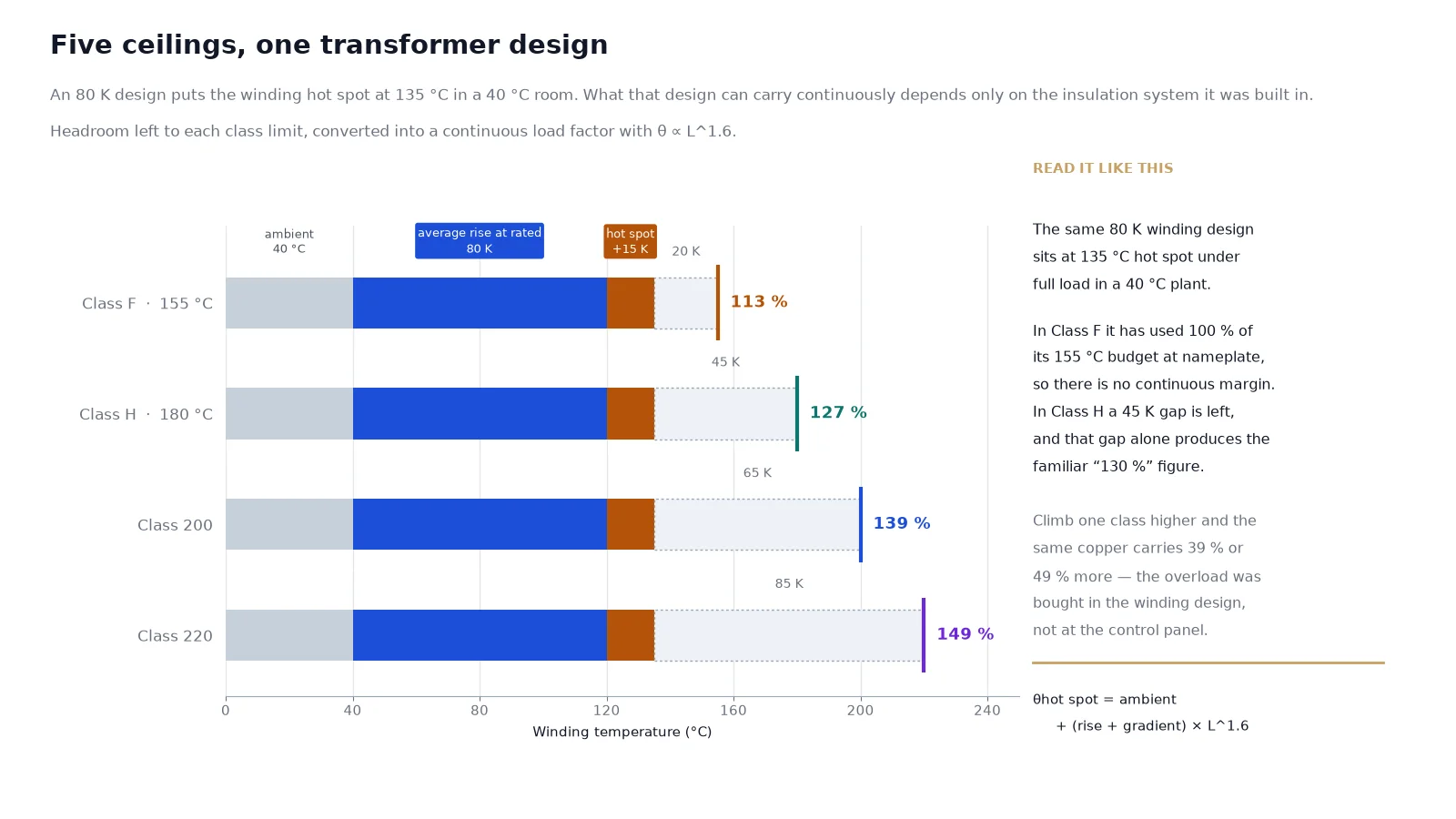
Notice what happens when the same 80 K winding is built in a Class F system instead. The hot spot at nameplate is still 135 °C, but the ceiling drops to 155 °C. The gap is now 20 K, and 20 K buys about 13% more current, not 30%. Same copper, same losses, same operating temperature throughout normal service, and less than half the overload capability, purely because of which resin and which impregnating varnish went into the insulation system.
This is the reason a supplier cannot answer “how much overload can this take” from a kVA figure. The question is answerable, but it needs the rise class and the thermal class, and most quotations only carry one of the two. If a datasheet states “Class H” without stating a rise, the overload capability is still unknown; Class H exists with 100 K, 115 K and 125 K designs, and each has a different ceiling.
The same relationships, plus the ageing limits behind them, are set out in more detail in the guide to transformer insulation class and temperature rise.
Winding temperature does not rise in proportion to current. It rises with the losses, and losses are dominated by the resistive term, which grows with the square of current, adjusted for how effectively the extra heat is carried away. In practice the relationship is well described by a simple power law:
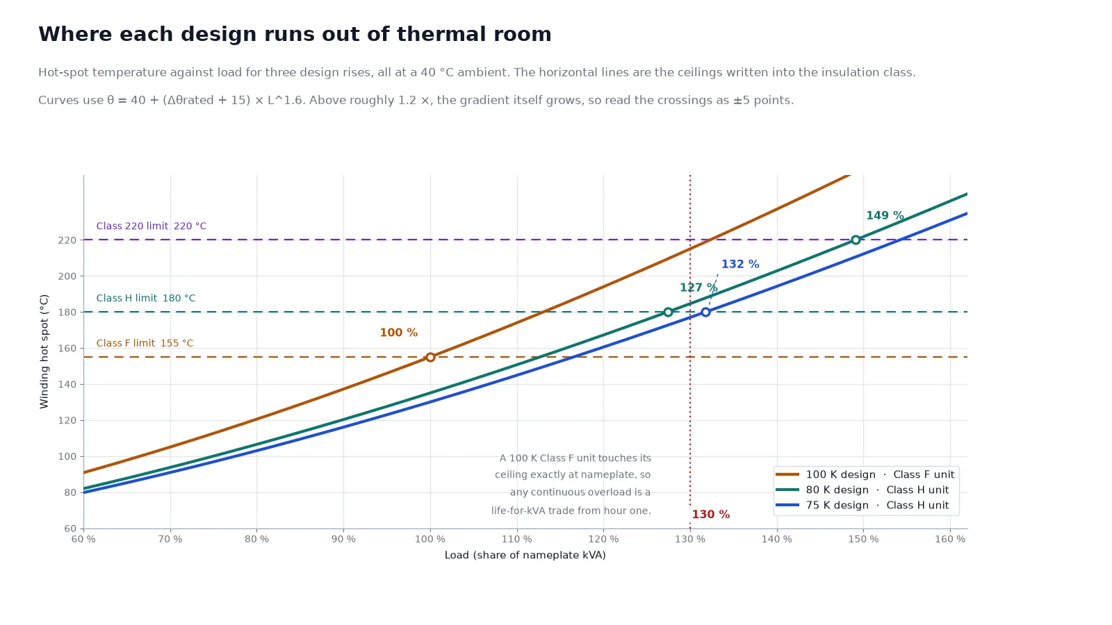
θhot spot = θambient + (Δθrated + G) × L^1.6
where L is the load as a fraction of nameplate, Δθrated is the design rise at nameplate and G is the hot-spot gradient. The exponent sits between about 1.5 and 1.8 for most air-cooled windings; 1.6 is a reasonable working value. Rearranged, it gives the load at which the hot spot reaches a chosen ceiling, which is the dry type transformer overload capacity for that specific unit:
Lmax = ((θlimit − θambient) / (Δθrated + G)) ^ (1 / 1.6)
Take a 1,000 kVA, 10 kV to 0.4 kV cast-resin unit with an 80 K design rise in Class H, installed where the summer ambient reaches 40 °C. The low-voltage rated current is about 1,443 A, so nameplate current is 1,443 A and a 130% duty means 1,876 A.
Running the equation at 130%: the rise multiplier is 1.30 raised to 1.6, or 1.52, so the hot spot lands at 40 + (95 × 1.52), or 185 °C. That is five degrees above the Class H limit. In other words, on this unit, 130% is not a continuous rating at all. It is a duty that must either be time-limited or supported by forced cooling, and any vendor who quotes 130% continuous for this specification is assuming a cooler room than the nameplate allows.
The load at which the hot spot actually reaches 180 °C on this unit is 127%. Push the design rise down to 75 K and the ceiling moves to 132%; build the same winding in a Class 200 system and it moves to 139%.
| Design rise at nameplate | Hot spot at nameplate, 40 °C ambient | Continuous ceiling in Class F | Continuous ceiling in Class H | Continuous ceiling in Class 200 | Continuous ceiling in Class 220 |
|---|---|---|---|---|---|
| 75 K | 130 °C | 119% | 132% | 144% | 155% |
| 80 K | 135 °C | 113% | 127% | 139% | 149% |
| 100 K | 155 °C | 100% | 113% | 123% | 132% |
| 115 K | 170 °C | no margin | 105% | 114% | 123% |
| 125 K | 180 °C | no margin | 100% | 109% | 117% |
| 150 K | 205 °C | no margin | no margin | no margin | 106% |
Treat the outputs as accurate to about plus or minus five points. Above roughly 120% the proportion of eddy and stray loss grows, the hot-spot gradient widens faster than the average rise, and the real ceiling comes in slightly below what the single-exponent model predicts. Ventilation, enclosure and harmonic content all shift it further.
Read the table in the direction that matters commercially. A 100 K Class F unit, which is a perfectly normal specification, has zero continuous margin: it hits its limit exactly at nameplate. Anything above nameplate on that unit is a life-for-kVA trade from the first minute. A 220 class winding at 100 K apparently reaches 132%, which is where a good part of the published “130%” claim actually originates.
Neither the IEC nor the IEEE loading guides hand out a single overload number. They define regimes, and the difference between them is intent and bookkeeping rather than physics. IEC 60076-12 covers dry-type loading specifically; IEEE C57.96 covers dry-type distribution and power transformers and is the framework most English-language procurement documents reference.
| Regime | What it assumes | Typical envelope | What it costs |
|---|---|---|---|
| Normal life expectancy loading | Load and ambient vary so that periods below nameplate offset periods above it; ageing stays near the design expectation | Up to about 110%, with a genuine daily load cycle | Nothing measurable over 20 to 30 years |
| Planned loading beyond nameplate | Recurring duty that is known in advance, evaluated against the actual unit, monitored, and accepted as a budgeted life cost | Evaluated case by case, usually 115% to 130% | A modest, accounted reduction in insulation life |
| Emergency loading | A contingency: one unit out, a feeder lost, a delay in replacement | Larger excursions for minutes to hours | A large, fast life cost, accepted to keep supply on |
The regime distinction matters because it changes what you are allowed to conclude. A 130% duty that occurs twice a year during changeover is emergency loading and can be approved on the back of a temperature reading. The same 130% occurring every weekday afternoon from June to September is not an emergency; it is a design decision that was made by default, and the correct response is capacity, not a loading guide.
One structural difference from oil-filled units deserves emphasis. Because there is no oil mass to absorb heat, the winding time constant of a dry-type unit is minutes rather than hours. The consequence is that pre-load matters far more. An oil-immersed transformer that has been sitting at 50% for six hours has a real thermal reserve to draw on when the load doubles. A dry-type unit at the same pre-load will be at its new temperature within twenty minutes, and the peak of the excursion is set almost immediately. Cooling class and the surrounding options are compared in transformer cooling classes.
The table that gets quoted most often comes from the ANSI treatment of low-voltage dry-type distribution transformers, and it is worth stating precisely because it is so often misread:
| Overload | Permitted duration | Condition |
|---|---|---|
| 125% of nameplate | 4 hours | A steady 50% load immediately before and immediately after the overload period; ambient within the nameplate reference |
| 150% of nameplate | 1 hour | |
| 200% of nameplate | 30 minutes |
Three things are easy to miss. First, the durations are conditional on the 50% pre-load and post-load; without that cool-down window the permissible times shrink, and for a unit coming off a 90% pre-load the numbers fall sharply. Second, the table is written for low-voltage distribution units, typically 600 V class, not for medium-voltage cast-resin substation transformers. Third, the same guidance is explicit that transformers are not designed for continuous overload capacity, which is the direct opposite of the way “130% continuous” gets used in sales conversations.
The right way to handle a varying load is not to pick a percentage but to reduce the whole day to an equivalent load:
Leq = √((L1²t1 + L2²t2 + … + Ln²tn) / (t1 + t2 + … + tn))
If the equivalent load for the cycle stays at or under 100%, the daily ageing is approximately normal no matter how spiky the profile looks. If it exceeds 100%, you are consuming life at a rate set by the hot-spot temperature during the peaks, and it is worth calculating rather than assuming.
Every one of the following spends part of the budget in the table above, and most installations have at least two of them. Each one reduces the dry type transformer overload capacity you actually have, without changing anything printed on the nameplate.
The 40 °C reference is a maximum, not an average. Because the ceiling depends on the difference between the limit and the ambient, every degree above 40 removes roughly 0.5% to 0.6% of continuous capacity on a typical Class H 80 K design, and the loss accelerates as the gap narrows. A room that hits 45 °C in summer has given away about 3% of capacity before any overload is applied, and the effect lands exactly when the load is highest.
Above 1,000 m the air that carries the heat away is thinner, and the temperature-rise limits have to be corrected. Practical correction tables land in the region of half a percent to one percent of capacity per 100 m, but the correction depends on the design and should come from the manufacturer rather than a rule of thumb. Enclosure is the same story from the other direction: a unit specified at IP54 or IP55 for a dusty or outdoor location loses natural convection, and winding rise can increase by 8 to 12 K relative to an open IP00 unit. Dust on the coil surface and in the cooling ducts is worse still, cutting heat transfer by 15% to 30% while adding nothing to the load calculation.
Harmonic currents raise the RMS current without raising the fundamental, and the eddy-current component of the winding loss grows roughly with the square of the harmonic order. A load that measures 85% on a true-RMS meter can already be at nameplate heating on a transformer that was designed for sinusoidal current. Where variable-frequency drives, rectifiers or large UPS systems dominate, the derating has to be based on the harmonic spectrum rather than on kVA, as set out in harmonic derating and K-factor selection. Phase imbalance is the quieter version of the same problem: total kVA looks acceptable while one phase runs materially hotter than the other two.
| Margin consumer | Effect on continuous capacity | How to detect it |
|---|---|---|
| Ambient above 40 °C | About 0.5% per K | Log the room temperature at peak hour, not the daily average |
| Altitude above 1,000 m | Roughly 0.5% to 1% per 100 m | Site survey; confirm correction with the manufacturer |
| Sealed enclosure, IP54 or higher | 8 K to 12 K more winding rise | Compare the actual rise at a known load with the test report |
| Dust in ducts and on coils | 15% to 30% loss of heat transfer | Infrared scan and visual inspection at each service |
| Harmonic-rich load | Set by the spectrum; often 10% to 20% | Power quality analyser at the transformer terminals |
| Phase imbalance | Local hot spot on one limb | Per-phase current logging, not total kVA |
Forced-air cooling is the cheapest way to buy overload capacity, and the least understood. The rule that governs it is simple: fans add capacity only if the manufacturer declared an AF rating for that unit. Fitting a fan kit to a transformer whose nameplate lists a single AN rating does not create a new rating, and the paperwork will not survive an insurance review.
Where an AF rating does exist, the uplift on substation-type dry transformers from roughly 225 kVA to 10,000 kVA can reach a third above the AN figure. That is more headroom than most continuous overload strategies deliver, and it is available on demand rather than as a permanent life cost. The trade is straightforward: fan power, fan maintenance, and the obligation to define what happens when a fan fails. A unit carrying 130% on forced cooling has to revert to its AN capability or shed load within the alarm window, and that logic belongs in the protection scheme, not in an operator’s memory.
Controller settings should follow the insulation class rather than a fixed number. As a starting range for a Class H unit, fans starting around 100 °C to 110 °C with a 10 K to 20 K differential to stop, an alarm stage well below the trip stage, and a trip setting that leaves margin under the class limit, will keep the transformer inside its rating without nuisance operations. The settings should be checked against the commissioning report for the specific unit.
Thermal arithmetic is only half the problem. The other half is that the electrical installation around the transformer was designed for a different assumption.
Under the NEC, transformer primary protection is sized at 125% of rated primary current for transformers with a primary current of 9 A or more, with the next standard device rating permitted where 125% does not correspond to a standard size. Feeders and branch circuits are sized at 125% of continuous load, and a continuous load is one expected to run for three hours or more. A sustained 130% duty therefore sits above both the protection setting and the conductor basis at the same time. In practice that means nuisance tripping during exactly the peaks the overload was meant to serve, and a temptation to raise the device rating, which quietly removes the transformer’s protection.
Nothing in Article 450 raises a transformer’s rating, and nothing in a loading guide changes what the protection is set to. If a 130% continuous duty is genuinely required, the protection scheme has to be reviewed alongside the thermal calculation, and the local authority has to be satisfied that the installation still complies. On medium-voltage installations where the protection is a relay package rather than a fuse, the same principle applies with more arithmetic: overcurrent settings are derived from rated current and coordination curves, not from a loading study.
The quantity the standards’ limits are written in is temperature, so temperature is what should be measured and recorded. Current-based judgement is an approximation that fails precisely in the cases that matter: a harmonic-rich load, an unbalanced load, or a unit with blocked cooling.
The difference between a managed overload and slow damage is almost entirely procedural. A workable discipline looks like this:
One diagnostic is worth more than all of the above. If overload events recur on a monthly rhythm, they are no longer emergencies. They are evidence that the installation is undersized, and the honest response is a capacity decision rather than a tighter procedure.
The 130% rule is a useful shorthand for one specific design, and a misleading one in five situations that are easy to recognise.
It is the wrong tool when the peak is daily rather than occasional, because a recurring overload is a sizing problem wearing an operating-procedure disguise. It is the wrong tool when the ambient already runs above 40 °C, because the headroom it describes has been spent before the load arrives. It is the wrong tool on a 100 K Class F unit, which reaches its limit at nameplate and has no continuous margin to trade. It is the wrong tool when winding temperature cannot be measured, because an unmonitored overload is an assumption rather than a decision. And it is the wrong tool for motor-starting currents, which are a voltage-drop and protection-coordination problem rather than a thermal one.
Where the rule does apply, it rewards the buyer who specified the margin in the first place. A 75 K rise in a Class H system, or a 220 class winding behind a cast-resin barrier, costs more at quotation and delivers a capability that cannot be retrofitted later: the ability to carry the peak without a capacity project. That is the only durable way to raise dry type transformer overload capacity, because it is bought in the winding rather than in the operating procedure. The trade is worth pricing explicitly when the load forecast is uncertain, which is most of the time. Our guide to transformer sizing and kVA calculation covers how to build the growth allowance into the rating instead of relying on overload headroom, and the dry-type insulation systems comparison explains what each thermal class costs in construction.
If you are specifying a dry-type unit against a known peak profile, send us the load cycle, the site ambient and the required continuous figure. We will size the rise class to the duty rather than quoting a percentage that may not apply to your installation.
Only if the design has the thermal headroom for it, which means a low rise class in a high insulation class. An 80 K winding in Class H reaches about 127% at a 40 °C ambient; a 75 K design reaches about 132%; a 100 K Class F unit reaches 100% and no more. The percentage is an outcome of the design, not an allowance that comes with the category.
It falls out of the thermal budget of a conservatively specified unit. An 80 K rise in a Class H system puts the hot spot at 135 °C at nameplate, leaving 45 K below the 180 °C ceiling, and 45 K converts to roughly a third more current. The same number also appears for a 100 K winding in a Class 220 system, which is a second legitimate route to it.
The opposite. A high rise class means the design is working hard at nameplate, so less thermal budget is left for anything above it. A 150 °C rise unit in a Class 220 system has only about 6% continuous margin. Rise class and overload capability move in opposite directions, which is why the two numbers have to be read together.
Yes, but only where the manufacturer declared an AF rating on the nameplate. On substation-type dry transformers the AF rating can be up to about a third above AN, which usually exceeds what any continuous overload strategy delivers. Fans retrofitted to an AN-only unit do not create a new rating.
For low-voltage dry-type distribution units the ANSI short-time guidance allows one hour at 150%, provided a steady 50% load precedes and follows the event. Medium-voltage cast-resin units should be assessed individually: the permissible time depends on pre-load, ambient and the design rise, and falls quickly as any of those worsen. Do not apply the low-voltage table to a medium-voltage unit.
Set them against the insulation class, not against a fixed number. For a Class H unit a typical arrangement is fans starting around 100 °C to 110 °C with a 10 K to 20 K stop differential, an alarm stage comfortably below the trip stage, and a trip setting that leaves margin under 180 °C. Confirm the final values against the unit’s commissioning report and the load profile.