Most transformer failures in the first two years are not manufacturing failures. They are installation failures that were invisible at handover: a plinth that was not level, a cable entry that was sealed against water but not against fire, an earth bond that was tightened onto paint, or a plant room with no calculable path for 15 kW of heat. Each of these is cheap to fix during construction and expensive to fix afterwards.
This guide covers the transformer installation requirements that decide whether the unit reaches its design life: foundation and loading, dielectric clearances, cable entry, earthing, and ventilation. The electrical acceptance tests that follow installation are a separate subject; they belong to pre-commissioning, and the sequencing matters because half of them cannot be performed correctly on a badly installed unit.
The five subsystems that define the installation
An installation is not one activity. It is five, and each has its own acceptance criterion. Treating them as a single “mechanical completion” milestone is how items get missed.
| Subsystem |
What it provides |
Acceptance criterion |
| Foundation and plinth |
Static support, level reference, oil containment |
Level within ±2 mm per metre; rated for transformer plus oil mass with a safety factor |
| Clearances and access |
Dielectric clearance to earth and between phases; maintenance working space |
Minimum in-air clearance per IEC 61936-1 for the Um of the system, plus design margin |
| Cable entry |
Mechanical support, bending radius, sealing, fire stopping |
Bending radius respected; entry sealed to the enclosure IP rating; fire barrier intact |
| Earthing and bonding |
Fault current path, touch voltage control, surge reference |
System resistance at or below design value; all bonds to a single electrode system |
| Ventilation |
Removal of full-load losses without exceeding the design room temperature rise |
Measured airflow and temperature rise at full load within the specified limits |
The choice between an outdoor pad-mounted arrangement and an indoor room changes the weight of each subsystem. The pole-mounted and pad-mounted comparison covers the outdoor case; this article focuses on the indoor and enclosure case where all five subsystems are compressed into one room.
Foundation and plinth
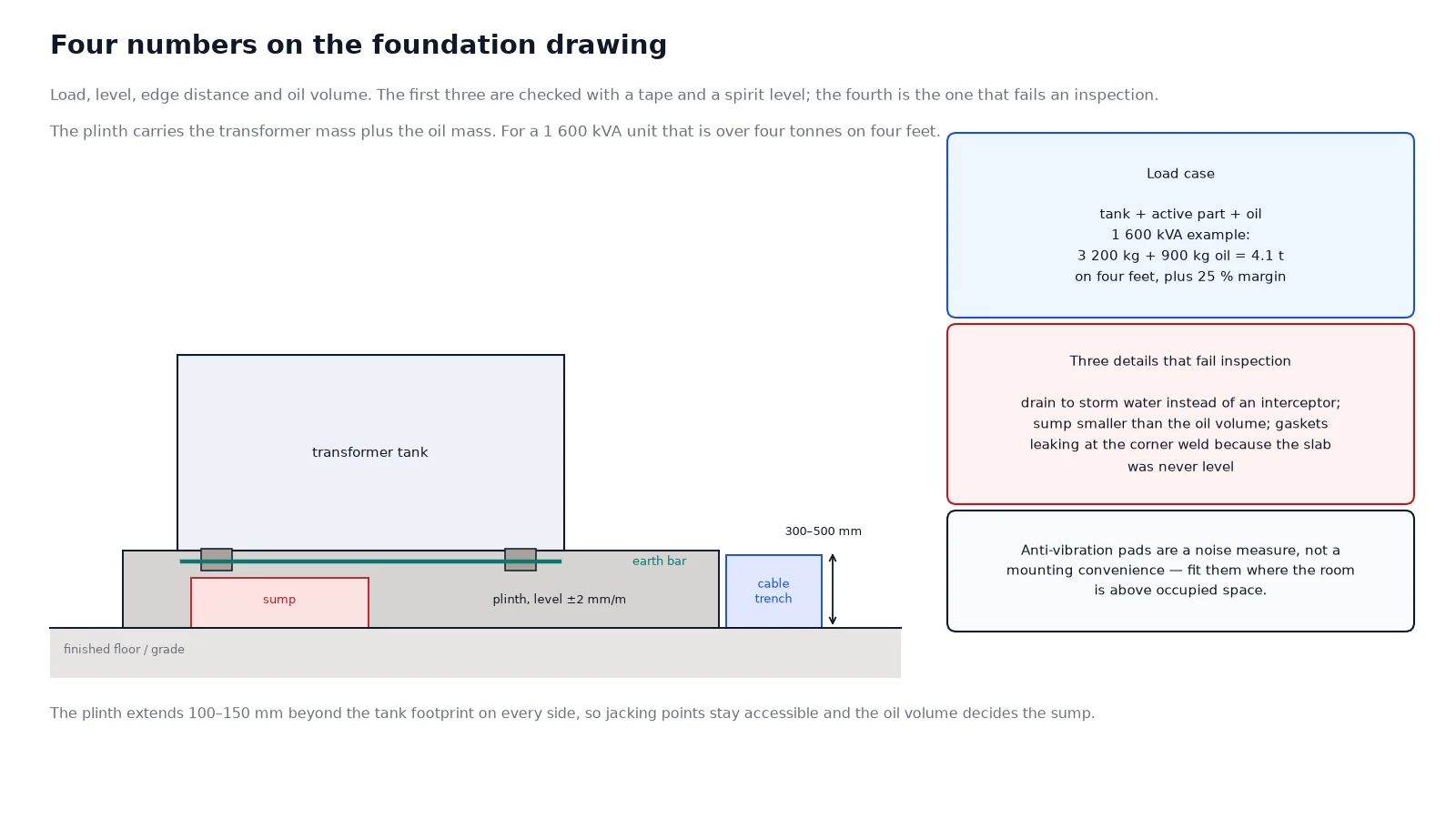
The plinth carries a static load and must not move. Two masses have to be added together: the transformer mass from the nameplate, and the oil mass, which for mineral oil is roughly 0.9 kg per litre. A 1,600 kVA oil-immersed unit might be 3,200 kg of active part and tank plus 900 kg of oil, so the civil design load is over four tonnes concentrated on four feet.
Practical requirements:
- Extend the plinth 100–150 mm beyond the tank footprint on all sides, so that rain running down the tank does not track onto the floor and so that jacking points remain accessible.
- Raise the top 300–500 mm above finished floor level for an outdoor or semi-outdoor installation, which keeps the cable box above standing water.
- Level within ±2 mm per metre. A transformer sitting on a 5 mm step loads two feet and unloads the other two; the tank distorts and the gaskets eventually leak at the corner welds.
- Fit anti-vibration pads under the feet where the room is above occupied space. This is a noise and structure-borne vibration measure, not a mounting convenience.
- Provide an oil containment pit or sump sized for the full oil volume of the largest unit, with drainage through an oil interceptor. A drain valve that discharges to the storm system is a code violation in most jurisdictions and an environmental incident waiting to happen.
For a dry-type unit the loading is lower and there is no oil, but the level and ventilation requirements are stricter, because the winding has no liquid to equalise temperature. The dry-type size and dimension reference gives footprint and mass for standard ratings, which is usually the fastest way to size a plinth during design.
Clearances: dielectric first, access second
Two different clearance numbers are needed and they are frequently confused. The dielectric clearance is the minimum air distance that the insulation system can withstand at the system’s highest voltage for equipment. The access clearance is the working space a person needs to inspect, test and torque connections.
IEC 61936-1 Annex A gives the minimum clearances in air as a function of Um. For the distribution classes relevant here, the phase-to-phase minimum is 75 mm at Um 12 kV, 125 mm at Um 24 kV and 180 mm at Um 36 kV. Designers normally apply a factor of 1.3 to 1.5 on top of the minimum, for three reasons: manufacturing tolerances on busbar and cable termination positions, pollution and humidity reducing the withstand of a nominally adequate gap, and the fact that a tool or a person’s hand will enter the space during maintenance.
| Requirement |
12 kV class |
24 kV class |
36 kV class |
| Minimum clearance in air (IEC 61936-1) |
75 mm |
125 mm |
180 mm |
| Typical design clearance applied |
100–125 mm |
160–190 mm |
230–270 mm |
| Front access for inspection and torque |
800 mm |
900 mm |
1,000 mm |
| Rear or side access where a cable box opens |
600 mm |
700 mm |
800 mm |
Height is the dimension that gets squeezed. A cable box needs room for the termination and for the bending radius of the cable, and a bottom-entry box in a low room forces either a shallow bend or a horizontal loop. Both reduce the dielectric margin at the point where the cable screen is cut back, which is the weakest point in the whole assembly.
Cable entry, bending radius and sealing
Bottom entry is the default for indoor installations because it protects the termination from drip and mechanical damage. Top entry is used where a cable trench is impossible, but it requires a properly gasketed, IP-rated entry plate and a drip loop outside the enclosure.
Three numbers control the mechanical side of the entry:
- Bending radius. Typically 12 to 15 times the cable outside diameter for medium-voltage XLPE, and 10 to 12 times for multicore. A 3-core 185 mm² cable of about 60 mm diameter therefore needs a 720–900 mm radius. If the room cannot give that, the cable size or the entry position has to change, not the rule.
- Support spacing. Cleats or tray supports at intervals that prevent the cable’s own weight loading the termination. Short-circuit forces on a 25 kA fault act on the cable as well as the busbar.
- Sealing. The entry must be sealed to the enclosure’s IP rating, and separately fire-stopped where the cable passes a fire compartment boundary. A sealing compound that meets the IP rating does not necessarily meet a fire rating; the two are different products and both are needed where the wall is a fire wall.
The enclosure rating itself should be selected for the actual environment rather than as a default. The IP rating guide explains which of the second-digit ratings actually exclude dust and which only exclude fingers, because an IP54 claim on a louvred enclosure is often IP2X in practice once the louvre is counted.
Earthing and bonding
Earthing has three separate jobs at a transformer, and a single conductor can rarely do all three well:
- Fault current return. The earth path must carry the earth fault current for the clearing time without exceeding the conductor’s thermal limit.
- Touch voltage control. Metallic parts that a person can touch must stay at a potential that is safe for the duration of the fault. IEC 61936-1 sets the permitted touch voltage by clearance time.
- Surge reference. The arrester earth, the tank earth and the LV neutral earth must be at the same potential during a lightning surge, or the difference appears across the winding.
The practical requirement is a single bonded electrode system with a resistance at or below the design value — commonly 10 Ω for a distribution installation and 1 Ω for a large substation. Two details cause most of the problems found on site. First, bonding to a painted tank flange: the paint insulates the bond, and the resistance measured with a clip-on meter reads fine because the meter is measuring the paint-free bolt. Second, using the cable armour or the LV neutral as the earth path, which works until the neutral carries fault current and raises the potential of every earthed enclosure on the LV system.
The earthing method also determines what the protection can see. A resistance-earthed system limits earth fault current to a few hundred amps, and the comparison of MV neutral grounding methods explains how that limit propagates into relay settings.
Ventilation: the calculation nobody does
Ventilation is the subsystem most often left to rule of thumb, and the one whose failure is slowest and most expensive. Every kilowatt of loss has to leave the room, or it heats the room until the transformer’s effective ambient rises and its insulation ages faster than the loading calculation assumed.
The calculation is one line:
Airflow (m³/s) = heat loss (kW) ÷ (1.2 × 1.005 × permitted temperature rise in K)
Work it through for a 1,250 kVA cast-resin unit with combined no-load and load losses of 15 kW at full load, in a plant room where the design permits a 10 K rise above outdoor ambient:
- Airflow = 15 ÷ (1.2 × 1.005 × 10) = 1.24 m³/s, or about 4,470 m³/h.
- Outlet grille free area at 2.5 m/s: 1.24 ÷ 2.5 = 0.50 m². A louvre has roughly 70% free area, so the gross opening is 0.71 m².
- Inlet grille at 2.0 m/s: 0.62 m² free, 0.89 m² gross.
Two refinements change the answer materially. The inlet must be low and the outlet high, on opposite walls where possible, so that the air actually crosses the winding rather than short-circuiting across the top of the room; and the outlet should be at least 20% larger than the calculated figure if the room has any obstruction such as a cable tray above the unit. Where the transformer has fans (AN/AF), the ventilation must be sized for the forced-cooled rating, not the natural one, because the fans exist precisely to push more loss out of the same winding.
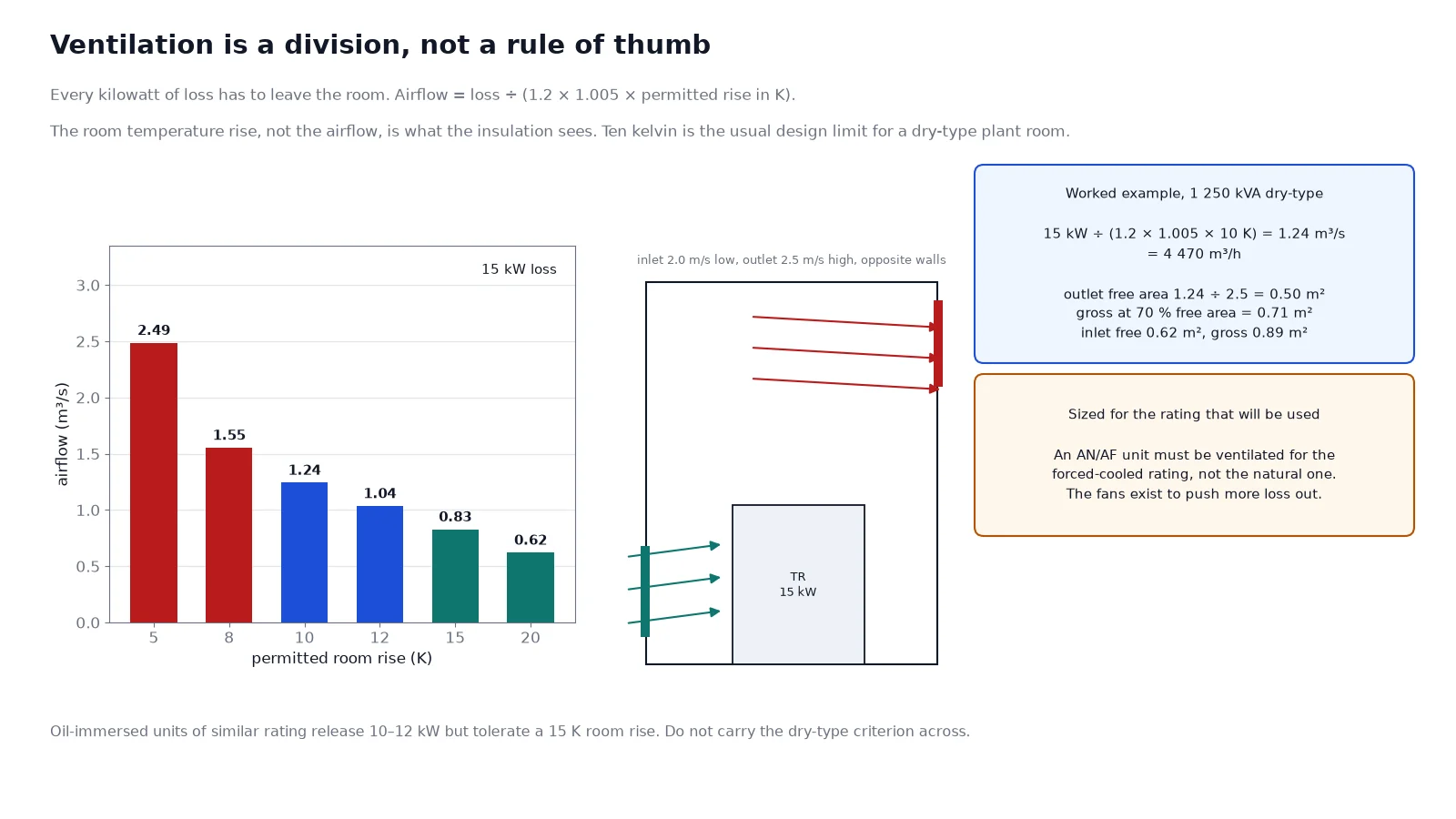
Oil-immersed units in the same rating range dissipate a similar loss but tolerate a higher room temperature rise, because the oil provides a thermal buffer and the radiators can be ducted. A 1,000 kVA oil-immersed unit at full load typically releases 10–12 kW, which needs a similar airflow but allows a 15 K room rise. Do not carry the dry-type criterion across to the oil unit or the reverse; the dry-type specification reference lists the losses that drive the calculation for standard ratings.
Fire separation and access
Fire requirements are a separate design discipline, covered in the fire protection options comparison, and are summarised here only as installation constraints, because they determine wall construction and the amount of floor area the unit occupies. An indoor oil-immersed transformer above a threshold rating normally needs a fire-rated compartment with oil containment; an F1-rated cast-resin unit is often accepted in the same room as the load without a separate compartment, which is why F1 is specified for buildings and data centres.
Confined installations concentrate all of these problems. Tunnel and underground substations add humidity, restricted access for lifting, and a ventilation path that has to be ducted rather than louvred. The metro and tunnel substation note covers the practical consequences for clearance, lifting and dehumidification.
Common installation mistakes
| Mistake |
Effect |
Correction |
| Plinth level taken at the four feet rather than the whole slab |
Tank distortion, gasket leaks, uneven loading |
Level the slab to ±2 mm/m before setting the unit; shim only for final adjustment |
| Design clearance used as installed clearance |
Reduced dielectric margin at the weakest point, usually the cable termination |
Verify the minimum at the termination, not at the busbar |
| Cable looped to meet a termination that is too close |
Bending radius violated; screen stress and eventual failure |
Relocate the entry or reduce the cable size; never bend below 12 × OD |
| Earth bond made onto a painted surface |
Bond resistance high but measurement appears acceptable |
Remove paint at the contact face, use a star washer, re-measure at the conductor |
| Ventilation sized by floor area rule of thumb |
Room temperature rise exceeds design; insulation ages faster |
Calculate from full-load losses and check the grille free area, not the opening |
| Fire stop omitted where the cable crosses a fire wall |
Fire compartment compromised; fails inspection |
Separate fire-stop product, listed for the wall type |
Frequently asked questions
What are the general requirements for installing a transformer?
Five: a foundation rated for the transformer plus oil mass and level within ±2 mm per metre; dielectric clearances per IEC 61936-1 for the system’s highest voltage with a design margin; cable entries that respect the bending radius and are sealed to the enclosure rating; a single bonded earthing system at or below the design resistance; and ventilation sized from the full-load losses for the permitted room temperature rise.
How much clearance is needed in front of a transformer?
Allow at least 800 mm for a 12 kV class unit, 900 mm at 24 kV and 1,000 mm at 36 kV, measured from the front face to any wall or obstruction. That is a working space for inspection, infrared scanning and torquing connections; it is additional to the dielectric clearance requirement.
Can a dry-type transformer be installed outdoors?
Only in an enclosure rated for the environment. A standard cast-resin winding is designed for indoor conditions — the environmental class on the nameplate, E1 or E2, defines condensation and pollution tolerance, not rain resistance. Outdoor installation requires a weatherproof enclosure with ventilation, and the IP rating of that enclosure governs.
How do I calculate the ventilation required for a transformer room?
Divide the full-load heat loss in kW by 1.2 × 1.005 × the permitted temperature rise in kelvin to get the airflow in m³/s, then divide by the permitted air velocity at the grille — 2.0 to 2.5 m/s is typical — to get the free area. Increase for the louvre’s free-area ratio, usually about 70%.
Does a transformer need its own earth electrode?
No, and it should not have one. The transformer tank, the surge arresters, the cable screens and the LV neutral must all be bonded to a single electrode system so that they rise and fall in potential together during a fault or a surge. Separate electrodes create a potential difference that appears across the winding.
What foundation is needed for an oil-immersed transformer?
A reinforced concrete plinth sized for the transformer mass plus the oil mass, extending 100–150 mm beyond the tank footprint, raised 300–500 mm above grade for outdoor installations, with an oil containment pit or sump sized for the full oil volume and drainage through an oil interceptor.
The takeaway
Installation requirements reduce to five numbers: the plinth load and its level tolerance, the clearance at the cable termination, the cable bending radius, the earth resistance, and the airflow. Get those right during construction and the transformer’s life is decided by its loading and its maintenance. Get them wrong and no amount of testing after the fact will recover the margin.
If you are preparing a plant room or an enclosure for a specific rating, send us the room dimensions and the transformer losses; we will return the clearance, ventilation and cable-entry envelope for that unit before the civil works are poured.