A factory acceptance test proves what left the works. It does not prove what arrived on site, sat in a yard for six weeks, was lifted by crane through a doorframe and filled with oil by a crew working in the rain. That gap is what a transformer commissioning checklist exists to close, and it is the reason a unit with a perfect routine test report can still fail within an hour of first energisation.
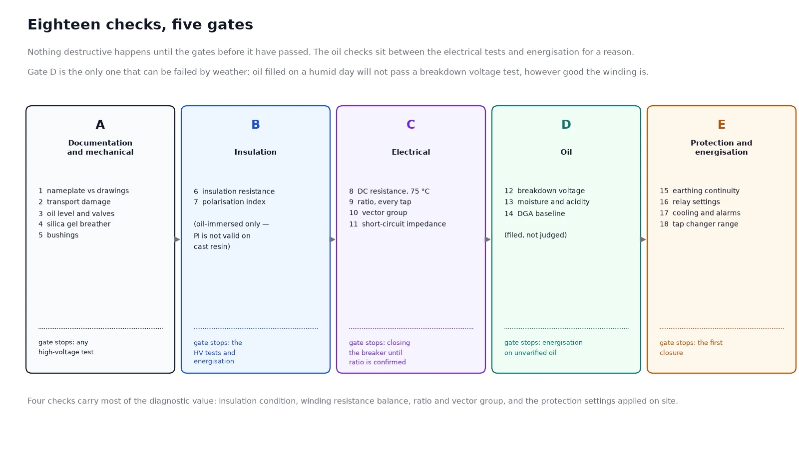
This guide gives eighteen checks in the order they should be performed, with the acceptance value for each. It applies to oil-immersed power transformers and to cast-resin dry-type units, with the differences noted where they matter. The order is deliberate: non-destructive and documentation checks come first, because they can stop a test that would otherwise damage the winding, and dielectric tests come after the oil has had time to settle.
Why the FAT is not a commissioning test
The routine test at the factory establishes that the unit matches its rating plate. Between that moment and energisation, four things can change:
- Mechanical disturbance. Transport and lifting can displace windings, loosen core clamping and shift the active part. A sweep frequency response comparison against the factory fingerprint is the only reliable way to detect it.
- Moisture ingress. Every opening — bushing covers, the conservator, the tap changer head — is a route for humid air. Oil absorbs moisture, and wet insulation loses dielectric strength far faster than the loading tables suggest.
- Assembly error. Bushing phase identification, CT polarity, earth bonding and tap changer position are all set by people on site, and all four are capable of producing a fault on the first energisation.
- System conditions. The protection settings applied on site are usually not the settings the factory assumed, and an inrush event will find any error.
For the factory side of the story, the testing and FAT guide explains which IEC 60076 tests are routine, type or special, and what the report should contain. Everything below assumes that report is already in hand.
The eighteen checks
| # |
Check |
Acceptance value or criterion |
| 1 |
Documentation cross-check |
Nameplate matches drawings, rating plate data matches routine test report, protection schedule present |
| 2 |
Transport damage survey |
No impact above the recorded g-level; no visible deformation, no oil seepage at welds |
| 3 |
Oil level, leaks and valve positions |
Level at the 25 °C mark for the actual oil temperature; all valves except drain and filter in open position |
| 4 |
Silica gel breather |
At least 75% of beads still active colour; oil cup filled to the mark |
| 5 |
Bushings |
No chips or hairline cracks; terminals torqued to spec; phase marking correct |
| 6 |
Insulation resistance |
Not below 70% of the factory value at the same temperature; minimum 1 MΩ per kV of winding rating plus 1 MΩ |
| 7 |
Polarisation index |
Oil-immersed units only: PI = R10/R1 ≥ 1.5 at 75 °C basis, investigate below 1.3 |
| 8 |
Winding DC resistance |
Corrected to 75 °C; phase balance within 2%; each phase within 2% of factory value |
| 9 |
Turns ratio at every tap |
Within ±0.5% of the nameplate ratio |
| 10 |
Vector group and polarity |
Matches nameplate, for example Dyn11 or YNd11; CT polarity correct for differential protection |
| 11 |
Short-circuit impedance |
Within ±7.5% of the guaranteed value where measured on site |
| 12 |
Oil dielectric breakdown voltage |
≥ 50 kV for units up to the 72.5 kV class; check against the project specification for the class in use |
| 13 |
Oil moisture and acidity |
Moisture ≤ 30 ppm for ≤ 72.5 kV class, ≤ 20 ppm above; acidity ≤ 0.03 mg KOH/g for new oil |
| 14 |
DGA baseline |
Recorded and filed as the reference for all future sampling; acetylene below detection limit |
| 15 |
Earthing continuity and resistance |
Tank, neutral, arrester and cable screen bonded to one electrode system; system resistance at or below design value, commonly 10 Ω |
| 16 |
Protection settings and trips |
Relay settings match the approved schedule; Buchholz, pressure relief, OTI and WTI trip tested by injection or by simulation |
| 17 |
Cooling and control circuits |
Fans or pumps start at the set temperature and current; interlocks and alarms proved through dry runs |
| 18 |
Tap changer operation |
Full range local and remote; limit switches stop travel; position indication matches the actual tap |
Before the first test: three preconditions
Three conditions must be met before any high-voltage test is applied. Skipping them produces readings that look bad and lead to unnecessary drying.
Oil standing time. After oil filling or filtration, a minimum of 48 hours of standing is normally required before electrical testing, and longer for large units. The purpose is to let entrained micro-bubbles rise out of the oil; bubbles collapse the breakdown voltage readings and can initiate partial discharge under test voltage.
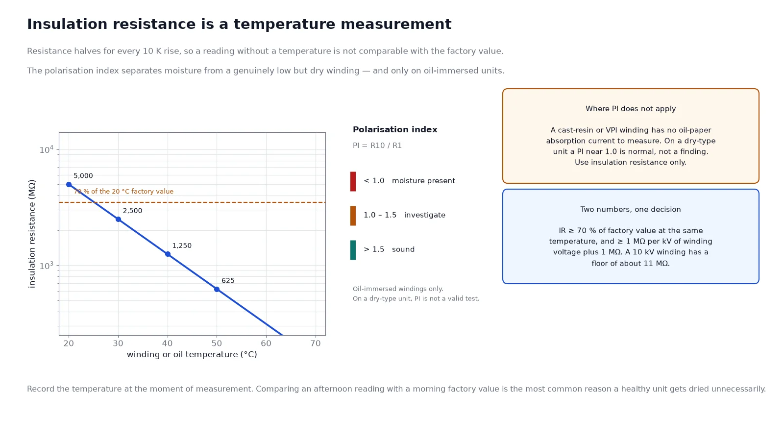
Temperature stability. Insulation resistance and winding resistance both depend strongly on temperature. Record the oil or winding temperature at the moment of each measurement and correct the result, rather than comparing an afternoon reading with a morning one. As a working figure, insulation resistance roughly halves for every 10 °C rise.
Instrument suitability. A 5 kV insulation tester is normal for oil-immersed windings at this voltage level. For dry-type windings the test voltage is lower, typically 500 V to 1 kV, because the test itself stresses the insulation more than it does in an oil-filled unit; the dry-type size and dimension reference gives the winding arrangement behind that difference. A megger with an inadequate guard terminal will give a reading dominated by surface leakage on a damp day, which is exactly the day people run these tests.
The checks that actually fail
Across a few hundred commissioning records, the failures cluster in a small number of places. The rest of the list is mostly verification.
Insulation resistance and polarisation index
Insulation resistance is measured from each winding to earth, with the other windings guarded, and from winding to winding. The absolute value matters less than the comparison with the factory figure at the same temperature, and the practical acceptance is that it should not be below about 70% of that value. A minimum of one megohm per kilovolt plus one megohm is the floor, not the target.
The polarisation index — the ten-minute resistance divided by the one-minute resistance — is the standard way to separate moisture from a genuinely low but dry insulation system. It is a useful test on oil-immersed windings in the 10 MVA and above range. It is not a useful test on cast-resin dry-type windings, where the insulation is a solid homogeneous barrier and the absorption current that PI depends on barely exists. Applying a PI criterion to an epoxy-cast unit and rejecting it for a reading of 1.1 is a common commissioning error.
Turns ratio and vector group
The ratio test is fast and catches the two errors that would otherwise appear as a differential trip on energisation: a tap changer left between positions, and a winding connected to the wrong tap. Test at every tap, not only the nominal one. A ratio outside ±0.5% is a factory conversation, not a site adjustment.
Vector group verification requires a three-phase source and a phase angle measurement, and it is the check most often skipped on units with a “standard” connection. It is also the check that catches a bushing phase swapped during reassembly. The consequence of a wrong vector group is a differential protection operation at the first energisation, which looks like a transformer fault and costs a day of investigation.
Winding resistance balance
Resistance is measured phase by phase with a micro-ohmmeter and corrected to 75 °C using the copper or aluminium temperature coefficient. Two acceptance criteria apply: phase-to-phase balance within 2%, and each phase within 2% of the factory value. A single high phase points to a loose connection, a broken strand or a tap changer contact that is not making properly.
The measurement has a trap. Winding resistance changes with temperature at roughly 0.4% per °C for copper, so a 5 °C difference between the phases during measurement produces an apparent 2% imbalance that does not exist. Let the unit stand until the oil is thermally stable, or correct each reading using its own measured temperature.
Oil tests and the DGA baseline
Breakdown voltage, moisture and acidity establish whether the oil is fit to be energised. The DGA baseline is different in kind: it is not a pass or fail test on the day, it is the reference point that makes every later sample interpretable. A unit commissioned without a baseline has no way to show that a gas concentration found two years later is new.
Take the sample from the bottom valve after flushing, in a syringe or a sealed container per IEC 60567, and record the oil temperature with the sample. The quality inspection process covers what the factory should already have measured before shipment, including the gas-in-oil result that becomes the reference for every later sample. Reading that first report is the subject of the DGA interpretation guide.
Protection, earthing and the first energisation
Protection settings are the last thing to verify and the first thing to get wrong. Four items cause almost all first-energisation trips:
- Inrush blocking. A differential relay set without adequate second-harmonic blocking will trip every time the transformer is energised. Check the blocking level against the relay’s inrush record, not against a default.
- CT ratio and polarity. A reversed CT on one side of a differential scheme produces a trip at any load. Draw the vector diagram rather than trusting the terminal markings.
- Neutral CT and earth fault settings. On a resistance-earthed system the earth fault current is limited by the resistor, and a pickup set for a solidly earthed system will never operate.
- Non-electrical trips. Buchholz, pressure relief valve, oil temperature and winding temperature trips should be proved by simulation and then re-armed before energisation. A Buchholz trip left in test position removes a layer of protection that will be needed for the first weeks.
Coordination between the LV main, the HV backup and the transformer damage curve belongs in the protection coordination guide. For the sequence itself, close the HV breaker five times with the LV side open, holding the first energisation for at least ten minutes and watching for abnormal sound, oil level movement and gas accumulation. Then leave the unit on no-load for a period — 24 hours is a common requirement — before applying load in steps. Listen during the no-load period: a steady hum at twice the supply frequency is normal, a crackling or popping sound is partial discharge and means the unit comes off.
The records that matter afterwards
A commissioning file is not paperwork. It is the only baseline against which every future test will be judged, and it takes about an hour to assemble properly:
- All eighteen results with the temperature at which each was measured
- The DGA baseline in ppm for each of the seven key gases
- The measured ratio at every tap, not only the nominal tap
- Photographs of bushing phase marking, earth bonds, tap position and nameplate
- The signed protection schedule, with the actual settings applied rather than the intended ones
Units with this file are diagnosable. Units without it generate arguments. The same principle applies to instrument transformers in the instrument transformer testing guide, where a ratio and polarity record made at commissioning resolves most later metering disputes.
Commissioning findings and their causes
| Finding |
Most likely cause |
Action |
| IR below 70% of factory value, PI below 1.3 |
Moisture ingress during storage or oil filling in humid conditions |
Hot oil circulation or vacuum drying; do not energise |
| One phase resistance high by 3–5% |
Loose busbar or tap changer contact; measurement at unequal temperatures |
Re-torque, re-measure with temperature correction, then compare again |
| Ratio deviation at one tap only |
Tap changer not seated, or a diverter contact fault |
Cycle the changer through full range several times, re-test |
| Differential trip at first energisation |
Inrush blocking inadequate, CT polarity reversed, or vector group mismatch |
Record the relay event, check polarity against the vector diagram |
| Buchholz alarm within hours |
Trapped air from filling, or genuine gassing |
Bleed, re-check; if it recurs, sample oil immediately |
| Abnormal noise on no-load |
Loose core clamping after transport, or overvoltage |
Measure applied voltage, then SFRA comparison against factory fingerprint |
Frequently asked questions
What is the difference between pre-commissioning and commissioning?
Pre-commissioning covers everything done before voltage is applied: documentation, mechanical inspection, insulation and electrical tests, oil tests and protection setting verification. Commissioning covers the energisation sequence itself and the first load trial — the impulse energisations, the no-load period and the stepped load run with temperature monitoring.
Is a polarisation index test required on a dry-type transformer?
Generally no. The polarisation index relies on the absorption current of a composite oil-paper insulation system, which a cast-resin or VPI winding does not have. On dry-type units, insulation resistance to earth and between windings at a reduced test voltage is the meaningful measurement, supplemented by partial discharge measurement where specified.
How long must oil stand before energisation?
A minimum of 48 hours after filling or filtration is the usual requirement for distribution and medium power units. For units of 72.5 kV class and above, the standard practice is to apply vacuum during filling and to hold it for a defined period, which replaces part of the standing time. Always follow the manufacturer’s instruction, because the required time depends on how the oil was processed.
What insulation resistance value is acceptable?
The practical criterion is a comparison, not an absolute: at least 70% of the factory value corrected to the same temperature, and above one megohm per kilovolt of winding voltage plus one megohm. A 10 kV winding therefore has a floor of about 11 MΩ, but a healthy unit of that size typically reads in the hundreds or thousands of megohms.
Can I energise the transformer before the oil test results arrive?
Only if the oil has been processed and verified by a site breakdown voltage test at minimum. Energising on unverified oil risks a dielectric failure that would otherwise have been prevented by a single day’s wait, and it invalidates the DGA baseline, since any gases present before energisation can no longer be separated from gases produced afterwards.
How many energisations should be made at first commissioning?
Three to five closures from the HV side with the LV open is the normal practice, holding the first for at least ten minutes. Repeated energisation exercises the inrush restraint in the protection and gives several opportunities to detect a mechanical problem before the unit is put on load.
The takeaway
Eighteen checks, four of which do the real work: insulation condition, winding resistance balance, ratio and vector group, and protection settings. Run them in the order given, record the temperature with every reading, and keep the DGA baseline — because the value of a commissioning record is entirely in the future comparison it enables.
If you are commissioning a batch of units and want the expected values for your specific rating, send us the nameplate data; we will return the acceptance band for insulation resistance, ratio tolerance and oil limits alongside the factory test report.