What instrument transformer testing actually covers
Instrument transformer testing splits into two groups that are often confused in a purchase order. Routine tests are run on every single unit before it leaves the factory, and the results travel with that unit. Type tests are run once on a representative design and are supplied as a report that covers the whole family. If your tender asks for “test reports” without saying which, you will usually receive the type reports and none of the routine results, which is the opposite of what a commissioning engineer needs.
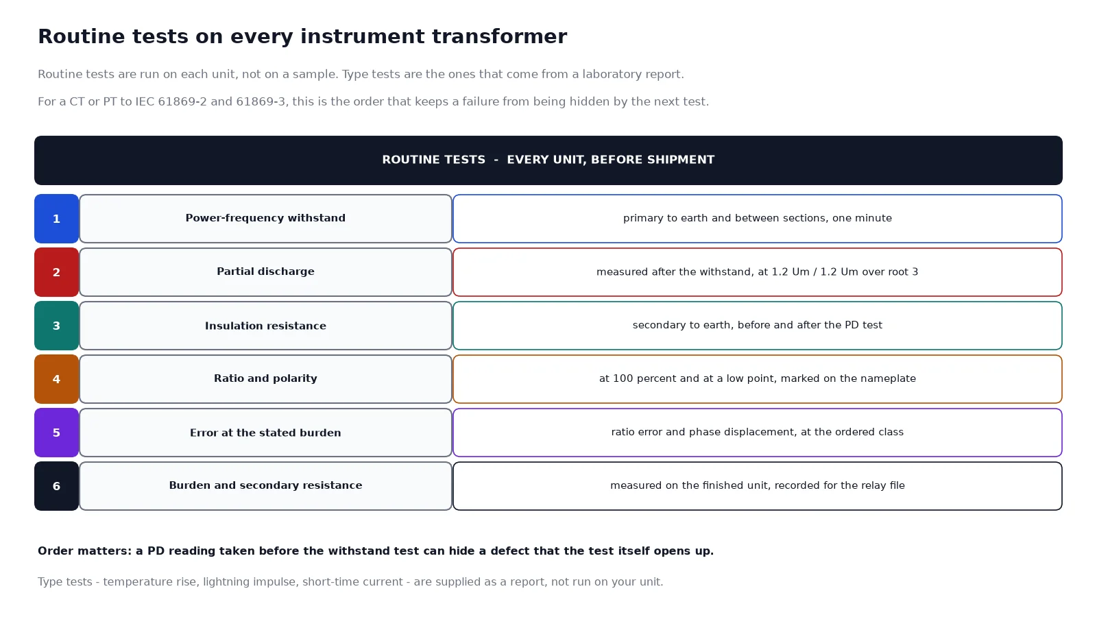
For current and voltage transformers to IEC 61869-2 and IEC 61869-3, the routine set is short and cheap: a power-frequency withstand, a partial discharge measurement, ratio and polarity, and error at the stated burden. Every one of those tests has a specific place in the sequence, and running them out of order can hide a defect rather than reveal one. The product family these tests apply to is indexed under instrument transformers.
The routine tests, in the order they are run
The order is not administrative. Each test is placed where it is because the previous one may open a defect that the next one would otherwise miss.
| Step |
Test |
What it proves |
Typical acceptance |
| 1 |
Power-frequency withstand |
Primary insulation holds at the specified test voltage for one minute |
No breakdown, no flashover |
| 2 |
Partial discharge |
No significant void discharge in the cast insulation |
Below the pC limit for the class |
| 3 |
Insulation resistance |
No moisture path or contamination |
Compared against the factory baseline |
| 4 |
Ratio and polarity |
The winding is the one ordered and is connected the right way round |
Within the class tolerance |
| 5 |
Error at stated burden |
Ratio error and phase displacement inside the class guarantee |
Within the limits for the ordered class |
| 6 |
Secondary resistance and excitation |
CT only – the data the relay engineer needs to set the protection |
Recorded, compared with design |
Ratio and polarity: the two facts a relay depends on
Ratio is measured by applying a known primary quantity and reading the secondary. On a voltage transformer that means a known primary voltage and a secondary voltmeter; on a current transformer a primary current, usually injected at a low value with the secondary loaded at its rated burden. The measured ratio is then compared with the nameplate and against the error limits for the class.
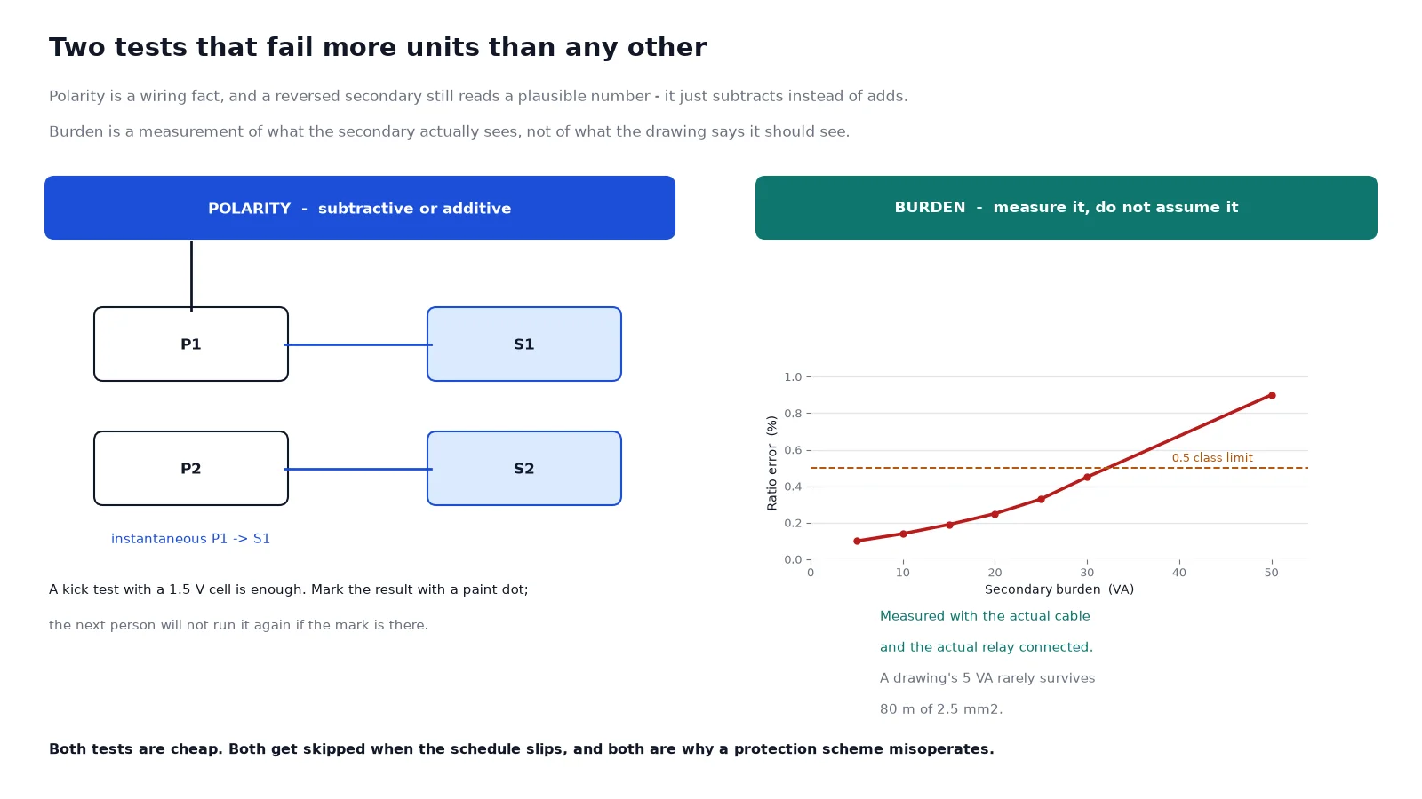
Polarity is a wiring fact rather than a measurement of quality. On a current transformer, P1 and S1 are marked so that current entering P1 at a given instant leaves S1 in the same direction – subtractive polarity, which is the standard for protection. A reversed secondary still produces a plausible current reading; it simply subtracts where the protection expects it to add, and a differential scheme with one reversed CT will operate on load.
The test itself takes seconds. A 1.5 V cell and an analogue millivoltmeter across the secondary is enough: flick the cell across the primary and watch the direction of the kick. Mark the result on the unit with a paint dot and record it, because the next person to work on the panel will not repeat a test that has already been done and signed.
Error at the stated burden: the test that depends on the order
Ratio error and phase displacement are measured at the burden written on the order, because the class guarantee only exists inside a stated burden range. This is where a specification and a test report can disagree without anyone lying: a unit ordered at 25 VA and tested at 25 VA passes, and then gets installed with 40 VA of connected burden and no longer holds its class.
On a current transformer the practical burden is the sum of the relay or meter, the wiring and the terminations. Wiring dominates more often than not. A 100 m loop of 2.5 mm2 copper is about 1.4 ohms, which at 5 A secondary is 35 VA – more than most protection relays. That single calculation explains a large share of “the CT is out of class” complaints, and it is why the ratio and burden selection tables are worth reading before the order rather than after commissioning.
The same logic on the voltage side is a voltage drop rather than extra VA, and the class limits themselves are described in the accuracy class guide.
Partial discharge: why it comes second
Partial discharge measurement is the most sensitive test in the list and the one most often skipped when a schedule slips. It is also the only routine test that can find a void inside a cast body which will fail years later rather than at commissioning.
The test is performed after the power-frequency withstand, deliberately. The withstand test stresses the insulation hard enough to open a marginal defect; a PD reading taken before it would show a clean unit that is no longer clean. Measurement follows IEC 60270, with the unit energised at 1.2 times the highest voltage for equipment and at 1.2 divided by root three, and the reading compared against the limit for its voltage class.
For cast-resin instrument transformers the limit is typically 10 pC at Um up to 12 kV, rising to around 20 pC at 24 kV and 50 pC at 36 kV. Treat those as the order of magnitude and confirm the exact figure and test procedure against the part of IEC 61869 that applies to your unit – a limit quoted to a tenth of a picocoulomb without a stated test voltage is not a specification.
Insulation resistance: a trend, not a pass mark
Insulation resistance is measured primary to earth, secondary to earth and primary to secondary, usually with a 500 V or 1,000 V insulation tester. There is no universal pass value, because the result depends on the tester, the temperature and the humidity of the day. What matters is the comparison: against the factory value for the same unit, and against the previous site reading.
A reading that halves between two annual tests is more informative than a reading that sits at a high absolute number. Record the temperature with the value, because insulation resistance roughly halves for every 10 degrees C rise, and a summer reading compared against a winter baseline will look like a fault when it is only weather.
CT-specific tests the relay engineer needs
Two results are not acceptance criteria but design data, and a report without them is incomplete for anyone setting protection.
- Secondary winding resistance. Measured per core, it is what lets the relay engineer calculate the actual connected burden and the knee point of the circuit rather than of the transformer alone.
- Excitation characteristics. A rising voltage applied to the secondary with the primary open gives the excitation curve, from which the knee point is read. Protection class CTs are defined by their composite error at the accuracy limit factor, and the excitation curve is how that behaviour is verified on the finished unit.
For a metering core the same data is less critical, because the core is specified by its instrument security factor rather than by its behaviour at many times rated current. Both are covered where the ratio is chosen, in the CT ratio selection tables.
Type tests, and which documents to ask for
Type tests are the ones a laboratory runs once on a design: temperature rise, lightning impulse, and for current transformers the short-time thermal and dynamic current test. They are not repeated on your unit, and asking for them per unit is a misunderstanding that costs weeks.
What a project documentation package should contain is a type test report for the design you are buying, the routine test certificate for each serial number you are buying, and the outline drawing for the frame. If the tender requires a specific laboratory or third-party witnessing, raise it at the inquiry rather than at shipment, because it changes the schedule and not the price.
The wider acceptance logic for power transformers – the sequence of a factory acceptance test and what a buyer should witness – is set out in the power transformer testing and FAT guide, and the same discipline applies at instrument transformer scale.
What to check on the routine test certificate
Six checks catch almost every documentation problem before the units are packed.
- Serial number matches the unit. Certificates photocopied from a previous order are more common than they should be.
- Ratio matches the order, including any residual winding. A three-winding unit certified as two windings is a rebuild, not a correction.
- Burden on the certificate matches the burden you specified. This is the single most common mismatch.
- PD value has a test voltage next to it. A number without a voltage is not a measurement.
- Polarity is stated as subtractive or additive, per core, not per unit.
- Secondary resistance is recorded per core for a CT, not as one averaged figure.
Field tests after installation
Factory results prove the unit. Field tests prove the installation, and they are a different set: primary injection or a secondary injection test through the actual wiring, a polarity check at the terminals with the relay in circuit, a burden measurement with the real cable connected, and an insulation resistance check after the panel is closed. A unit that passed every routine test can still be commissioned with its secondary shorted by a test link that was never removed.
On a residual circuit the field test matters even more, because the three units are now a set. A polarity error on one of three residual windings produces a standing voltage in the broken delta, and the earth-fault relay either loses sensitivity or trips on load. The earthing arrangement that the protection is designed around is described in MV neutral grounding methods.
FAQ
Is a partial discharge test mandatory on every unit?
For cast-resin instrument transformers at medium voltage it is a routine test in the applicable IEC 61869 part, so it belongs on every unit rather than on a sample. If a supplier offers it only as an option, ask which standard the unit is being built to.
How long does the power-frequency withstand test take?
One minute at the specified test voltage for the insulation class. The test voltage itself comes from the Um of the unit, not from the nominal system voltage.
What is the difference between ratio error and composite error?
Ratio error is a metering figure at rated current or voltage. Composite error is a protection figure that includes the harmonic content of the secondary current during a fault, and it is what the 5P or 10P class is defined by.
Can I accept a CT with a knee point lower than the design value?
Only if the connected burden is low enough that the protection still meets its accuracy limit factor. A low knee point with a heavy burden is exactly the combination that makes a differential scheme misoperate.
Why does the burden on the certificate matter so much?
Because the accuracy class is only guaranteed inside the rated burden. A certificate issued at a lower burden than the one installed does not cover the installation.
Do I need to repeat routine tests on site?
No, but you do need to test the installed circuit: wiring, polarity at the relay, actual burden and insulation resistance. Those are installation tests, and they find different faults from the factory ones.
The short version
Ask for two documents, not one: the type test report for the design and the routine test certificate for each serial number. On the certificate, check that the ratio, the burden and the polarity per core match your order, and that the partial discharge figure carries its test voltage. Then, at site, measure the burden with the real cable connected, because that is the number that decides whether the class you paid for survives installation. For units built for outdoor duty where pollution and housing construction change the test emphasis, the 35 kV outdoor CT selection guide covers the additional checks.