A 35 kV outdoor current transformer spends its life doing something mundane and unforgiving: stepping a feeder current down to 5 A or 1 A so a meter and a relay can read it, in weather, for thirty years, without an oil leak. The LZZBW-35 outdoor current transformer is the pillar-type cast-resin answer to that job, and it is one of the few devices on a 35 kV bay where a wrong choice is discovered only at commissioning, when the meter reads low or the protection relay will not pick up.
This guide explains what the outdoor current transformer 35 kV designation means, how to choose the ratio and the accuracy class from the load rather than from habit, what the outdoor environment imposes on the casting, and how the cast-resin pillar compares with the oil-immersed outdoor CT that it usually replaces. If you are specifying a whole 35 kV bay, the current transformer range covers the indoor cast-resin units that pair with it.
Reading LZZBW-35
The type designation is a specification in miniature. Each letter removes an option.
| Character |
Meaning |
What it tells the buyer |
| L |
Current transformer |
This is a CT, not a voltage transformer |
| Z |
Pillar, post type |
Stands on a base plate; not a through-wall or bushing type |
| Z |
Cast resin insulation |
Epoxy cast body, no oil and no gas to maintain |
| B |
With protection winding |
A 10P protection core is part of the design, not an add-on |
| W |
Outdoor |
UV and pollution resistant casting, not for indoor cubicles |
| 35 |
Rated voltage 35 kV |
Highest voltage for equipment is 40.5 kV |
| A / B |
Mechanical version |
Two outline variants of the same electrical design, for different mounting heights |
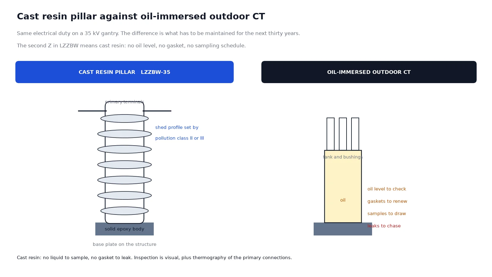
The two-Z construction is the detail worth noticing. “Cast resin” here means a solid epoxy body, and it is why this family has no oil level to check, no gasket to leak and no sampling schedule. That is a maintenance argument, not only an environmental one: on an outdoor gantry, the cost of sending a crew up to a leaking oil CT every few years exceeds the price difference between the two technologies.
Published ratings
| Parameter |
Value |
Comment |
| Rated voltage |
35 kV |
Highest voltage for equipment 40.5 kV |
| Rated insulation level |
40.5 / 95 / 185 kV |
Power frequency, then lightning impulse |
| Rated frequency |
50 Hz or 60 Hz |
Stated at order |
| Rated primary current |
Specified per project |
The ratio is a design input, not a stock item |
| Rated secondary current |
5 A or 1 A |
Decided by the cable run and the relay |
| Accuracy class |
0.2S, 0.5 for metering; 10P for protection |
Two cores are usual on a feeder bay |
| Rated output, burden |
10 to 20 VA |
Project specific; larger burdens need a larger core |
| Short-time thermal current |
Up to 80 kA for 1 s |
Must exceed the fault level at the installation point |
| Rated dynamic current |
Up to 160 kA peak |
Twice the thermal value, as the standard requires |
| Pollution level |
Class II or Class III |
Customizable; Class III for coastal and industrial atmospheres |
| Standards |
IEC 60044-1, GB 1208 |
The older IEC series; IEC 61869-2 is its successor |
Two of these rows decide most of the trouble. The short-time thermal current has to be checked against the fault level at the bay, because a CT that is electrically correct and thermally undersized will be destroyed by the first through-fault. And the rated output has to be checked against the actual burden, which is the subject of a later section.
Choosing the ratio
The starting rule is that the CT must not saturate at the maximum load current the feeder will carry, and the ratio should be the next standard step above it with a margin. Standard ratios climb through 50, 75, 100, 150, 200, 300, 400, 500, 600, 800, 1,000 and 1,200 A on this frame class, and the choice is usually driven by the transformer or line rating behind it.
| Feeder rating |
Maximum load current at 35 kV |
Typical ratio |
| 5 MVA transformer |
about 82 A |
100/5 or 100/1 |
| 10 MVA transformer |
about 165 A |
200/5 or 200/1 |
| 16 MVA transformer |
about 264 A |
300/5 |
| 25 MVA transformer |
about 412 A |
500/5 |
| 40 MVA transformer |
about 660 A |
800/5 |
Two refinements matter more than the base rule. First, the metering core and the protection core do not have to share a ratio. A 400/5 metering core with a 400/5 protection core is common, but where the fault level is high and the relay needs a good lower end, a metering core one step lower than the protection core gives better accuracy at light load. Second, on a feeder that supplies a transformer with a known overload policy, the ratio should reflect the overload rather than the nameplate, because a ratio sized exactly at nameplate will saturate during a legitimate overload and the meter will under-record exactly when it matters. On a feeder like that, the 35 kV transformer selection guide is the other half of the calculation.
The ratio arithmetic, the standard steps and the effect of the secondary current are worked through in the CT ratio selection guide, which is the right companion piece if the feeder rating is not yet fixed.
Accuracy class and burden: the pair that fails together
An accuracy class is a promise made at a stated burden. A 0.2S core rated 15 VA keeps its 0.2S accuracy up to 15 VA of connected burden and no further. The burden is the sum of the relay or meter VA, the lead resistance and the joint resistance, and on a long outdoor run the leads are often the largest of the three.
| Class |
Where it belongs |
Note |
| 0.2S |
Revenue and tariff metering |
Extended range, accurate from about 1 percent to 120 percent of rated current |
| 0.5 |
Check metering, internal energy accounting |
Adequate where the reading is not the billing basis |
| 10P |
Overcurrent and earth-fault protection |
The number is the composite error at the accuracy limit factor |
The S in 0.2S is what makes it suitable for a feeder that runs light at night. A plain 0.2 class core is specified for accuracy at rated current and drifts at low current; the S variant extends the accurate range down towards a few percent of rated current, which is exactly the band a distribution feeder spends most of its time in.
For the protection core, the accuracy limit factor is the multiple of rated current up to which the core still meets its composite error. A 10P20 core stays within 10 percent up to 20 times rated current. Check that figure against the maximum through-fault current divided by the CT ratio, and remember that a core chosen for metering accuracy is not automatically suitable for protection. The accuracy class guide works through the 0.2S, 0.5, 5P and 10P definitions in full.
5 A or 1 A secondary
The choice is a cable-length decision. A 1 A secondary produces one fifth of the current for the same burden, and since the VA lost in the leads is proportional to the square of the current, the 1 A option allows a much longer run for the same lead cross-section. On a 35 kV outdoor gantry with the marshalling kiosk a hundred metres away, that difference is real.
The trade is that a 1 A secondary needs more turns on the core, which makes the CT slightly larger and more expensive, and that some older relays and meters are only offered with 5 A inputs. Where the relay is being replaced at the same time as the CT, 1 A is usually the better long-run choice; where the CT is being replaced under an existing panel of 5 A devices, staying at 5 A avoids a change of everything downstream. The same cast-resin construction appears indoors at 10 kV, and the LZZBJ9-10 and LZZBJ12-10 comparison covers that side of the range.
What “outdoor” adds to the design
An indoor cast-resin CT and an outdoor one can carry the same electrical ratings and still not be interchangeable. The outdoor version has to survive conditions the indoor one never sees.
- Creepage and shed profile. Pollution class II covers most inland sites; class III is the right choice for coastal installations, cement plants, chemical plants and anywhere the insulators on the same gantry already show tracking.
- UV exposure. The casting and the surface finish are formulated for continuous sunlight. Repainting an indoor unit and putting it outside is not equivalent.
- Rain and condensation. The shed profile is designed so water does not bridge between sheds, and the base is sealed against water ingress from the mounting plate.
- Base mounting on a structure. A pillar CT has a flat base that bolts to a steel frame or a concrete plinth. The outline drawing, the bolt pattern and the terminal height all have to suit the structure, which is why the A and B mechanical versions exist.
- Primary connection loads. The primary terminals carry the line or cable lug, and the conductor weight and thermal expansion load have to be taken by the structure rather than by the casting.
Cast resin against oil-immersed outdoor CT
Both technologies are still in service on 35 kV networks, and the choice is a maintenance decision more than an electrical one.
| Item |
Cast resin pillar, LZZBW type |
Oil-immersed outdoor CT |
| Insulation |
Solid epoxy, no liquid |
Transformer oil, sealed tank |
| Routine maintenance |
Visual inspection and cleaning |
Oil level, oil quality, gasket condition, sampling |
| Leak risk |
None in service |
Real, and the main reason these units get replaced |
| Partial discharge behaviour |
Dependent on casting quality; voids are the failure mode |
Dependent on oil condition and moisture |
| Fire and spill |
No liquid to spill |
Oil containment required in some jurisdictions |
| Repairability |
Replace the unit |
Some field repair possible |
| Typical failure to watch |
Surface tracking in heavy pollution |
Moisture ingress and oil degradation |
The comparison is not a claim that cast resin is universally better. Oil-immersed units remain common where very high ratios or very high thermal currents need a larger core than a casting can carry economically. But for a metering and protection CT on a 35 kV distribution feeder, the cast-resin pillar removes an entire maintenance routine, and that is why it dominates new installations.
Secondary safety rules that are not optional
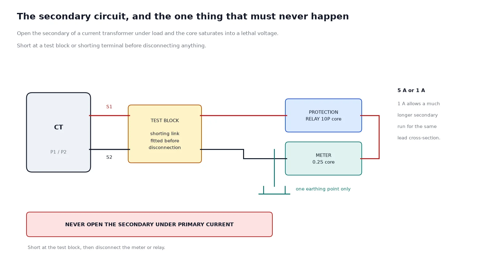
A current transformer is the one instrument transformer that must never be open-circuited on the secondary while primary current flows. With the secondary open, the core saturates and the voltage across the open terminals rises to a level that destroys the insulation and can kill the person who opened it.
- Short the secondary across the terminals before disconnecting any meter or relay, using a dedicated shorting terminal or a test block designed for the purpose.
- Earth the secondary at one point only, normally at the CT star point or at the first marshalling terminal.
- Do not rely on a screw terminal as the shorting point; use a shorting link on a test block.
- Label the polarity at both ends. P1 and P2 on the primary, S1 and S2 on the secondary, with the polarity mark consistent through the whole circuit.
Commissioning tests
| Test |
What it proves |
| Insulation resistance, primary to secondary and to earth |
No moisture path or casting damage |
| Ratio check by primary injection or by secondary voltage method |
The ratio matches the nameplate and the cores are not crossed |
| Polarity check |
The relay sees the correct direction of current |
| Secondary winding resistance and burden measurement |
The connected burden is inside the rated VA |
| Power-frequency withstand on the primary |
The insulation level has survived transport and installation |
| Partial discharge, where specified |
Casting quality; a void inside the epoxy shows up here rather than in service |
Ordering checklist
State the system voltage and the highest voltage for equipment, the ratio for each core, the accuracy class and rated output for each core, the secondary current, the short-time thermal current and dynamic current required by the fault level, the pollution class, the altitude, the mechanical version if the mounting height is constrained, and the standard to which the tests will be witnessed. Add the outline drawing requirement and, for a project order, the routine test report format.
With those items the unit is built once. Without them the ratio gets confirmed late, the burden is discovered at commissioning, and a second order follows.
Frequently asked questions
What does LZZBW-35 mean?
It is a current transformer, pillar type, cast-resin insulated, with a protection core, for outdoor use, rated 35 kV with a highest voltage for equipment of 40.5 kV. The A or B suffix identifies the mechanical outline variant.
Is the LZZBW-35 oil immersed?
No. The second Z denotes cast-resin insulation, so the body is solid epoxy with no oil. Oil-immersed outdoor CTs exist in the same voltage class, but this family is the dry alternative and needs no oil maintenance.
Which accuracy class do I need for billing?
0.2S for revenue metering, because the S extends the accurate range down to a few percent of rated current. Class 0.5 is adequate for check metering where the reading is not the billing basis.
Why does my meter read low at light load?
Either the core is a plain 0.2 rather than a 0.2S, or the connected burden exceeds the rated VA and the core is saturating early. Measure the actual burden before changing the CT.
Can I use a 5 A CT on a long secondary run?
It is possible but wasteful: lead losses rise with the square of the current, so a 1 A secondary is the better choice beyond about fifty metres. Where the downstream devices are all 5 A, keep 5 A and increase the lead cross-section instead.
What pollution class should I specify near the coast?
Class III, and confirm the creepage distance in millimetres against the site’s pollution level. Class II is intended for inland, lightly polluted sites and will track prematurely in a salt-laden atmosphere.
How often does a cast-resin CT need maintenance?
Visual inspection and cleaning of the sheds, typically with the bay outage cycle, plus a thermographic check of the primary connections. There is no oil to sample and no gasket to renew, which is the main operating advantage over the oil-immersed type.
Send the single-line diagram, the fault level and the metering scheme, and the ratio, the accuracy class and the burden can be fixed together rather than one at a time. That is the difference between a CT that commissions cleanly and one that has to be reordered after the first meter reading is questioned. Send the bay data to our engineers and the outline drawing comes back with the ratio already confirmed.