LZZBJ9-10 and LZZBJ12-10 are both 10 kV indoor cast resin current transformers in a pillar-type housing, both epoxy-cast, both used for metering and protection in medium-voltage switchgear. On a one-line diagram they look interchangeable, and many projects treat them that way. The differences show up in four places: system frequency, winding arrangement, secondary terminal design and the accuracy combinations each series publishes.
This comparison sets the two side by side using the published data, then reduces the choice to the questions that actually change the order. If you are new to the device family, the instrument transformer accuracy class guide explains the accuracy codes first; the full current transformer range shows the rest of the 10 kV options.
What the Two Series Share
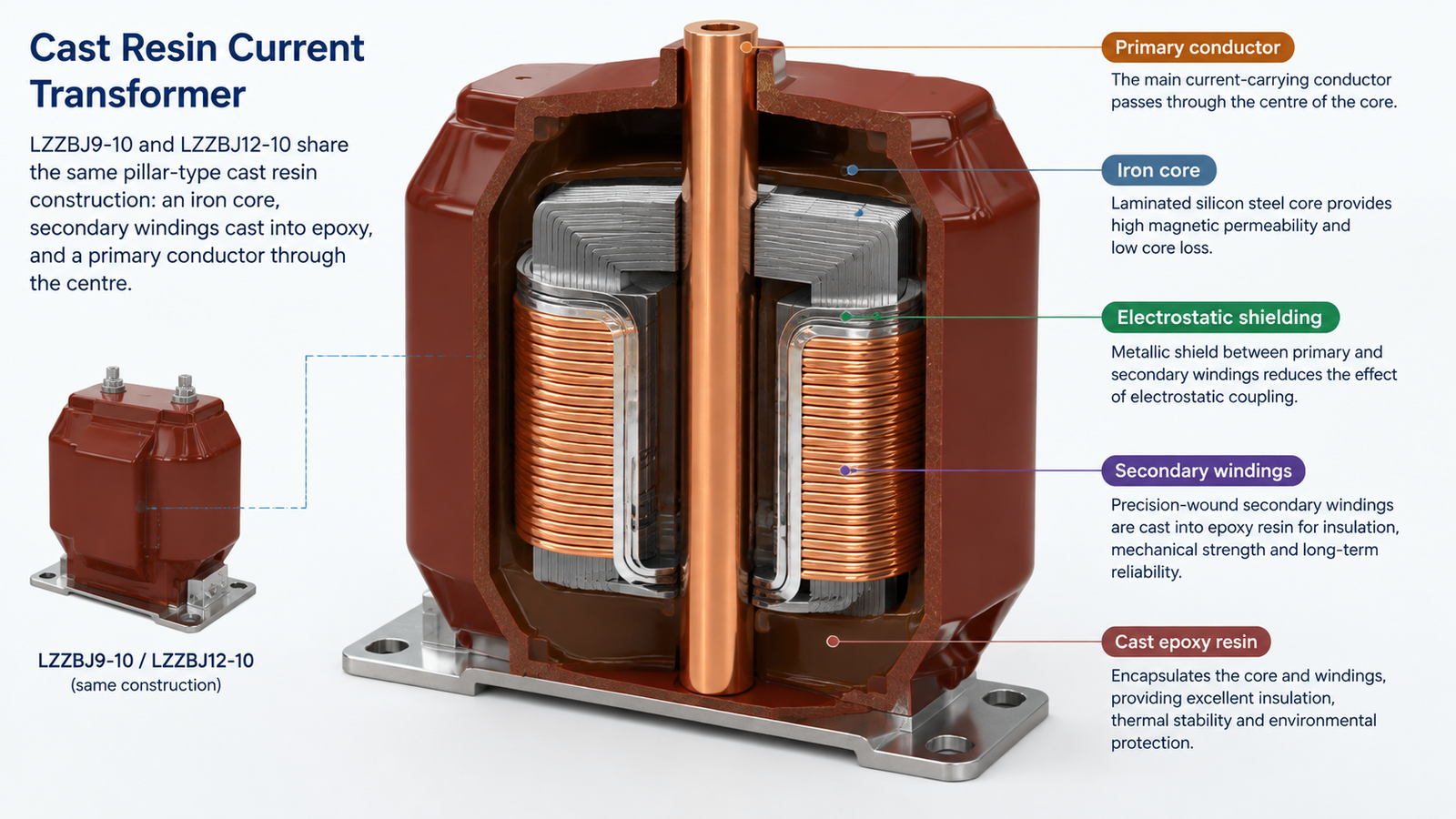
Both are indoor, single-phase, epoxy-resin-cast current transformers for 10 kV systems. Both use a pillar or support-type structure with the primary conductor passing through the centre and the secondary windings cast into the resin body. Both are intended for measurement, energy metering and relay protection circuits in air-insulated switchgear, and both are built to IEC and GB practice with partial-discharge control in the casting.
That shared base is why the price difference between them is small and why buyers default to whichever is in stock. The reasons to choose one over the other are specific:
The Five Real Differences
Parameter
LZZBJ9-10
LZZBJ12-10
Rated frequency
50 Hz
50 / 60 Hz
Primary current range
5 A to 1,000 A published, with 1 A or 5 A secondary
Selected per configuration
Dual ratio
Published for 200/5/5 A, 400/5/5 A and similar double-ratio forms
One metering class plus one protection class, or two protection classes
Accuracy classes published
0.2, 0.2S, 0.5, 5P10, 5P15, 5P20, 10P10
Metering and protection classes per configuration
Rated burden
10 / 15 / 20 / 30 VA
Per configuration
Insulation level
12/42/75 kV, with 24/65/125 kV available
10 kV class
Secondary terminal arrangement
Standard terminal block
Shielded outlet with connection holes on the face and side, three exit directions
Core
Per configuration
Imported core with controlled heat treatment
Environment
Altitude up to 1,000 m, -5 °C to 40 °C, humidity below 90% at 20 °C
Suited to humid and heavily polluted areas
Three of these rows decide most orders. The rest are configuration detail.
Difference 1: 50 Hz or 50/60 Hz
This is the row that disqualifies the LZZBJ9-10 from a whole category of projects. Its published data is 50 Hz only. The LZZBJ12-10 is published for 50 Hz and 60 Hz.
Frequency matters for a current transformer because the core flux is inversely proportional to frequency. A transformer designed and gapped for 50 Hz operated at 60 Hz runs at lower flux and is thermally safe, but its ratio and phase error shift slightly and its accuracy certificate no longer describes the installed condition. The reverse — a 60 Hz design on a 50 Hz system — is the dangerous direction, because flux rises and the core can saturate earlier, which distorts protection current and can overheat the secondary circuit.
For export projects to 60 Hz markets, marine installations, and plants with 60 Hz generators, order the LZZBJ12-10. For a 50 Hz network, either series works and the decision moves to the next row.
Difference 2: Dual Ratio and Dual Core
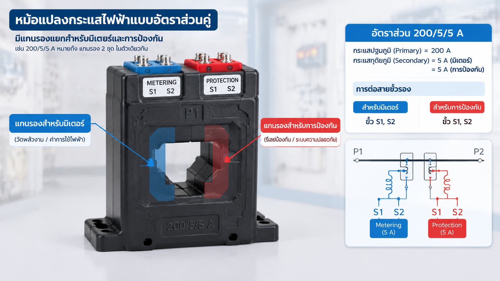
The LZZBJ9-10 publishes double-ratio forms such as 200/5/5 A and 400/5/5 A. In that notation the primary has a tapped winding giving two ratios — 200 A and 400 A — and there are two secondary cores, each 5 A. A single unit therefore covers two metering ranges, which is useful where the load grows over the life of the installation or where a feeder is initially lightly loaded and later expanded.
The LZZBJ12-10 is described with one metering class and one protection class, or two protection classes, in the same housing. That is a different arrangement: the two cores serve different functions rather than different ratios. Metering gets the accurate core, protection gets the core with the higher saturation and the P-class accuracy limit.
For most switchgear the functional split is what you need, because the relay and the meter have different requirements and neither cares about the other’s ratio. Dual ratio becomes valuable in retrofit work, in feeder bays with uncertain future load, and in projects that want to postpone a CT replacement by one capacity step.
Difference 3: Secondary Shielding and Terminal Access
The LZZBJ12-10 documents an electrostatic shield at the secondary outlet terminal, with connection holes on the face and the side face, so the secondary leads can exit in three directions. Two practical problems disappear with that design.
First, cable routing in a crowded cable chamber. Three exit directions mean the CT can be installed without rotating the whole unit to suit a fixed terminal position, which matters where the primary bar geometry is fixed by the switchgear.
Second, tamper resistance. A shielded secondary outlet with limited access makes it harder to short or bypass a metering core from outside the panel — the reason the series is often specified for utility metering points and landlord-tenant billing installations where revenue metering is exposed to the customer side.
Difference 4: Accuracy Classes and Burden
The LZZBJ9-10 publishes a wide class menu: 0.2 and 0.2S for metering, 0.5 for general measurement, and 5P10, 5P15, 5P20 and 10P10 for protection, with rated burdens of 10, 15, 20 or 30 VA. The table pairs classes to primary current bands, which is the detail most quotations omit.
Primary current band
Typical class combinations published
Rated output
1 s thermal current
Dynamic current
5 to 100 A
0.2/0.5, 0.2S/0.2, 0.5/10P10, 0.2S/10P10
10 / 10 VA, 10 / 15 VA
22.5 kA
44 kA
200 to 300 A
As above
10 / 15 VA
24.5 kA
44 kA
400 to 600 A
As above
15 / 20 VA
45 kA
90 kA
800 to 1,000 A
As above
20 / 30 VA
63 kA
100 kA
Read the last two columns as the short-circuit strength of the primary circuit, not of the secondary. A CT on a feeder with a 25 kA fault level must have a published thermal current above that figure for the specified duration, and the dynamic current above the peak. This is the check that catches most misapplied CTs, because buyers compare ratios and accuracy and skip the thermal column.
Burden follows from the connected load, not from the CT. Add the relay or meter burden, the lead burden and any test-block burden, then compare with the rated output at the chosen class. The guide to CT ratios and VA ratings walks through that arithmetic with worked figures.
Difference 5: Insulation Level and Environment
The LZZBJ9-10 publishes 12/42/75 kV, with a 24/65/125 kV option. The 12/42/75 kV figure is the standard 12 kV class insulation level used in Chinese-market switchgear, so the CT can sit in a 12 kV panel even on a 10 kV system. That flexibility matters where a project standardises on 12 kV switchgear and wants one CT for both.
The LZZBJ12-10 is described as suitable for humid and heavily polluted areas, with a fully enclosed cast body and anti-pollution design. In coastal, tropical or heavy-industry environments that wording is worth more than a small accuracy advantage, because pollution-induced surface tracking is what actually kills cast resin CTs in service.
Which One to Order
Situation
Recommendation
Reason
60 Hz system, marine or export project
LZZBJ12-10
Published 50/60 Hz; LZZBJ9-10 is 50 Hz only
Revenue metering exposed to the customer side
LZZBJ12-10
Shielded secondary outlet with restricted access
Humid, coastal or heavily polluted site
LZZBJ12-10
Anti-pollution fully enclosed design
Feeder with expected future load growth
LZZBJ9-10 dual ratio
200/5/5 A or 400/5/5 A covers two ranges in one unit
Wide accuracy menu needed for a mixed relay set
LZZBJ9-10
0.2S through 10P10 published with burden options
Crowded cable chamber with fixed bar geometry
LZZBJ12-10
Three secondary exit directions
Panel standardised on 12 kV switchgear
LZZBJ9-10
12/42/75 kV published, with a 24 kV option
Five Mistakes When Specifying Either Series
Mistake
Consequence
Fix
Comparing ratios only
Thermal or dynamic rating below the fault level; CT destroyed in a fault
Check 1 s thermal and dynamic current against the fault study
Ignoring the burden arithmetic
Class not held at the actual connected load; metering error out of tolerance
Add relay, lead and test-block burden, then compare with rated output
Ordering a 50 Hz CT for a 60 Hz system
Accuracy certificate no longer valid; ratio and phase error shift
Specify LZZBJ12-10 or confirm a 60 Hz design
Using a metering core for protection
Core saturates during a fault; relay sees a fraction of the current
Use the P-class core for protection and keep the cores separate
Assuming dual ratio means dual function
Only one ratio is active at a time; the second ratio is not a second protection core
Confirm whether the secondary is tapped ratio or a second core
What to Put on the Enquiry
System voltage and insulation level required, 12/42/75 kV or higher.
Rated primary current and whether a dual ratio is needed.
Secondary current, 1 A or 5 A, and the number of cores.
Accuracy class for each core, metering and protection.
Rated burden in VA for each core, with the connected load stated.
System frequency, 50 Hz or 60 Hz.
Short-circuit level and duration at the installation point.
Mounting orientation and available secondary cable exit directions.
Environment: indoor humidity, pollution level, altitude and ambient range.
Standards, and whether a type test report is required for approval.
Conclusion
LZZBJ9-10 and LZZBJ12-10 are close enough that the choice usually comes down to two questions: does the system run at 60 Hz, and does the metering point need tamper-resistant secondary access. If either answer is yes, take the LZZBJ12-10. If the project needs a dual ratio, a wide accuracy menu, or a 12 kV insulation level in a 10 kV system, take the LZZBJ9-10. In both cases the thermal and dynamic current ratings deserve more attention than the ratio, because they are what the CT has to survive.
The code breaks down as: L for current transformer, ZZ for post or pillar type cast resin insulation, B for double secondary winding protection, J for increased capacity or a specific design variant, 9 for the design number, and 10 for the 10 kV voltage class. The LZZBJ12-10 follows the same convention with design number 12.
Can LZZBJ9-10 be used on a 60 Hz system?
Its published data is 50 Hz. A 50 Hz design energised at 60 Hz runs at lower flux, so it does not saturate earlier, but its ratio and phase errors move away from the certificate values. For a 60 Hz project specify the LZZBJ12-10, which is published for 50 Hz and 60 Hz.
What is 200/5/5 A on a current transformer?
It describes a dual-ratio primary with two secondary cores. The primary winding has a tap giving 200 A and 400 A ratios, and each of the two secondary cores delivers 5 A. It is not two protection cores; the two cores can be assigned to metering and protection, but the ratio is selected by primary connection.
Why does thermal current matter more than ratio?
Because the primary winding carries the full fault current. If the published 1 s thermal current is below the feeder fault level, the CT is destroyed during a fault regardless of how accurate it is in normal operation. The dynamic current rating covers the first peak of the fault and is checked separately.
Which series is better for a coastal substation?
The LZZBJ12-10 is described for humid and heavily polluted areas with a fully enclosed anti-pollution cast body and an imported, heat-treated core. In salt-laden air, surface pollution performance decides service life more than a small accuracy difference does.
Can I order a 1 A secondary instead of 5 A?
Yes, the LZZBJ9-10 publishes 1 A, 2 A and 5 A secondary options. A 1 A secondary reduces lead burden, which helps where the CT is far from the relay panel; the trade-off is a higher secondary voltage at the same VA, so confirm the relay’s input range.
Fixed and withdrawable VS1 breakers interrupt the same fault current. The difference is isolation, testing and replacement time - here is how to choose.