Transformer protection coordination is the discipline of making several relays agree in advance about which one trips first. Every transformer is covered by at least three overlapping schemes — differential, earth fault and overcurrent — and each of them will happily operate for the same fault. The engineering is not in making them operate; it is in making the correct one operate first, the backup operate only if the first fails, and none of them operate for a fault that is not theirs.
The failure mode when this goes wrong is rarely a missed trip. It is a trip on the wrong device: an HV breaker opening for an LV feeder fault and taking a whole board offline, or a differential relay operating on inrush every time the transformer is energised. Both are coordination failures, and both are visible on paper before commissioning if anyone plots the curves.
What each zone is responsible for
| Scheme |
ANSI device |
Zone |
Operating time |
Role |
| Differential |
87T |
Between HV and LV CTs, including the winding |
1–2 cycles |
Main protection for internal faults |
| Restricted earth fault |
64REF |
Winding to the neutral point |
Instantaneous |
Earth faults near the neutral, where overcurrent is blind |
| HV overcurrent |
51 / 50 |
HV side, looking into the transformer |
Definite or inverse |
Backup for the transformer and for the LV bus |
| LV main overcurrent |
51 / 51N |
LV busbar and outgoing circuits |
Inverse |
Primary for LV bus faults, backup for feeders |
| Mechanical |
63 / 26 / 49 |
Oil, winding and top-oil temperature |
Minutes |
Slow developing faults and overload |
| Instantaneous LV |
50 |
Close-in LV bus fault |
Instantaneous |
High-current faults, blocked for through faults |
The rule that follows from this table is that every fault should be cleared by the innermost zone containing it, and every outer zone should be slower by a deliberate margin. Where the margin collapses, the scheme still works on a good day and miscoordinates on a bad one.
The damage curve is the ceiling
All of these curves must sit below one line: the transformer’s through-fault withstand. IEEE C57.109 defines damage curves for liquid-immersed transformers as a function of through-fault current and duration, and for dry-type units the equivalent limit comes from the winding thermal capability — the same family of limits described in the IEC, IEEE and GB standards map. Above that line, the winding is being damaged even if it has not yet failed.
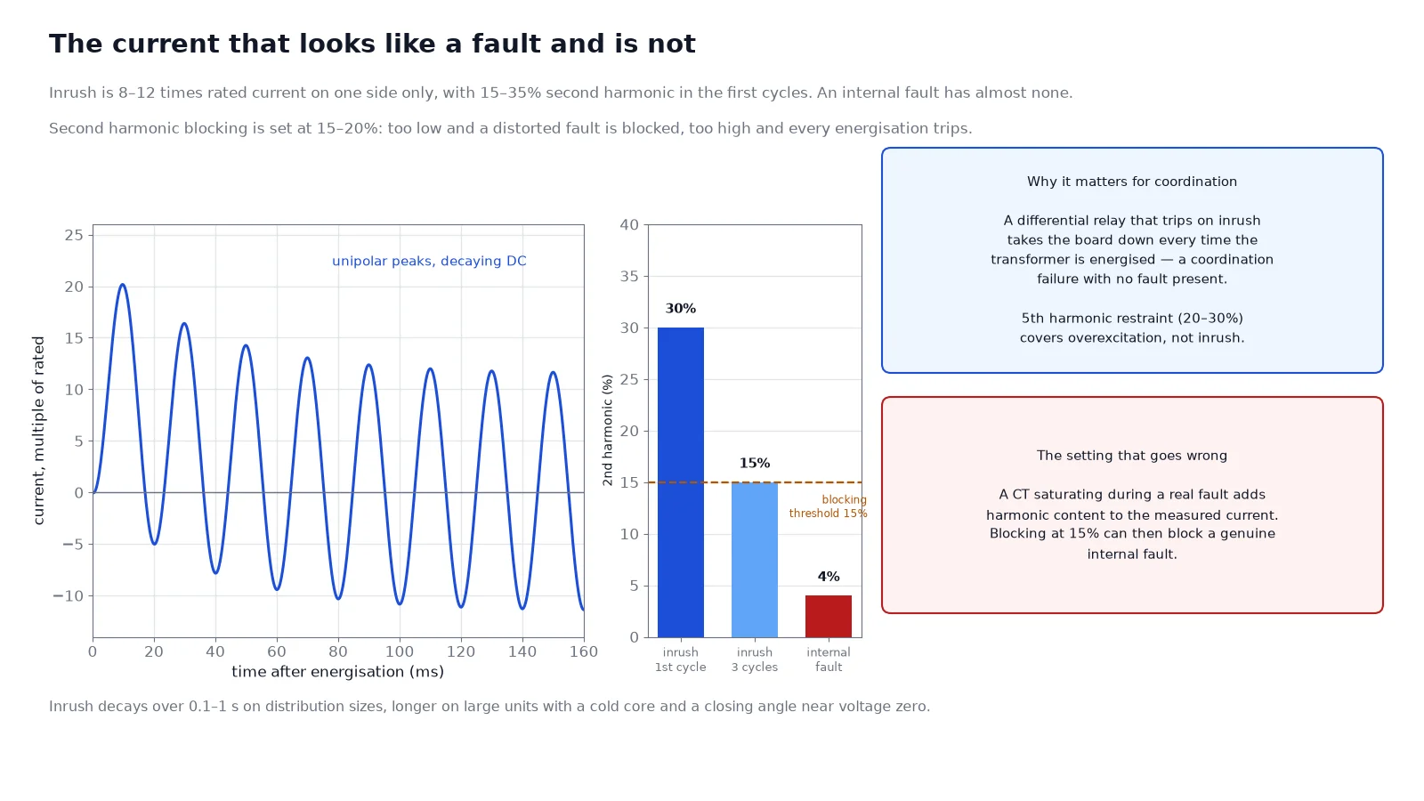
The practical consequence is a two-sided constraint. The relay curve has to be above the downstream device’s curve by a coordination interval, and below the damage curve with a margin of 10–20% in time. When the two constraints cross — which happens on small transformers with high impedance and long backup times — the answer is not to squeeze the margin but to add a scheme: REF covers the winding, differential covers the transformer, and the overcurrent element stops being the primary protection for anything except the busbar. The %Z figure that sets these currents is covered in percentage impedance and short-circuit voltage drop.
Inrush: the fault current that is not a fault
Energising a transformer draws a current that looks, to a differential relay, exactly like an internal fault: 8 to 12 times rated current on the energised side, with nothing on the other side, decaying over a few cycles to a few seconds depending on the core and the point on the voltage wave where the breaker closes. The current is rich in second harmonic, typically 15–35% during the first cycles, and that is what the relay uses to tell the two apart.
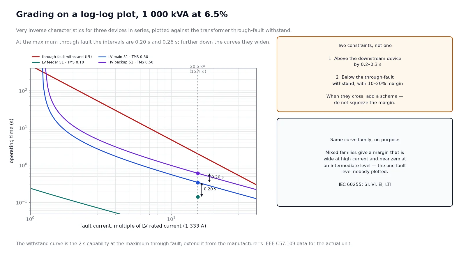
Second harmonic blocking at 15–20% is the standard defence, usually combined with waveform symmetry analysis and, on modern relays, with cross-blocking between phases. Two settings deserve attention. The blocking threshold must be low enough to block genuine inrush on a cold core but high enough not to block a real fault that happens to be mildly distorted — and a fault with a CT that is saturating can produce second harmonic content that a naive setting will read as inrush. Fifth harmonic restraint, set at 20–30%, covers overexcitation rather than inrush, and is a separate element.
CT dimensioning for through faults
A differential relay compares two currents that should be equal, so during an external fault both CTs must reproduce a very large current faithfully. If one saturates and the other does not, the difference appears as a false differential current and the relay operates on a fault outside its zone. This is the classic cause of unexplained 87T operations.
For a 1 000 kVA, 11/0.433 kV unit at 6.5% impedance, a close-in LV fault produces about 20.5 kA on the LV side, which is 15.4 times the LV rated current of 1 333 A. A 5P20 CT is nominally rated for 20 times rated primary current, but the accuracy limit factor assumes a specified burden; add the relay, the leads and the secondary wiring resistance and the real factor may fall below 15. The check is arithmetic, not catalogue reading: required ALF equals the maximum through-fault multiple divided by the CT rated primary current, times the ratio of actual to rated burden. Transient performance adds a further dimensioning factor, because the DC component of an offset fault current saturates a core that the AC calculation says is fine.
The coordination time interval
Grading between two inverse-time relays is done with a coordination time interval, which covers the downstream breaker’s interrupting time, the relay’s overshoot and a margin for errors. With numerical relays the interval is commonly 0.2–0.3 s; with electromechanical relays it is 0.3–0.4 s. Below that, the backup element will occasionally beat the primary element to the trip, and the event will look like a random misoperation.
The curve families matter more than the interval. IEC 60255 defines standard inverse, very inverse, extremely inverse and long-time inverse characteristics, and mixing families between two relays in series produces a margin that is large at high currents and small at low ones, or the reverse. The general practice is to keep the same family through a grading pair so the curves stay roughly parallel on a log-log plot.
A worked grading example
Take a 1 000 kVA, 11/0.433 kV transformer at 6.5% impedance. HV rated current is 52.5 A, LV rated current 1 333 A, and a close-in LV fault gives 20.5 kA on the LV side — 15.4 times LV rated, and 807 A seen by the HV relay, which is 15.4 times HV rated. Using very inverse characteristics (t = 13.5 × TMS / (M − 1), where M is the current multiple):
| Device |
Pickup |
TMS |
At 20.5 kA LV fault |
At 4 kA LV fault |
| LV feeder 51 |
200 A |
0.10 |
0.14 s (at M = 102) |
1.06 s (at M = 20) |
| LV main 51 |
1 600 A |
0.30 |
0.34 s (M = 12.8) |
2.70 s (M = 2.5) |
| HV backup 51 |
66 A |
0.50 |
0.60 s (M = 12.2) |
4.86 s (M = 2.4) |
At the maximum fault the intervals are 0.20 s between feeder and main, and 0.26 s between main and HV backup. Further down the curve the intervals widen to 1.6 s and 2.2 s, because the pickup multiples converge as the current falls. That widening is the reason the same curve family is used throughout: with a mix of families, the second interval could just as easily shrink to zero at some intermediate current, and the miscoordination would only show up for one particular fault level.
Where coordination actually breaks
- LV fuses instead of relays. A fuse has no settable curve and a steep one. Above a certain fault current the fuse beats the upstream relay comfortably; just above its threshold it may not, and that is where the grading has to be checked numerically.
- Downstream generation. A generator on the LV board contributes fault current that the HV relay does not see, so the HV backup becomes slower or blind for bus faults. This is the case that forces busbar differential or a transfer trip.
- Motor contribution. Large motors feed the fault for the first few cycles, raising the LV fault level well above the transformer’s contribution and pushing the instantaneous elements into a range where they must be blocked.
- Reclosing. A transformer that has just cleared a through fault is hotter and weaker than the damage curve assumes; repeated reclosing into the same fault is how a survived fault becomes a failed winding.
- Settings drift. Relay settings changed during commissioning and never documented are the most common source of later misoperation, and the reason the as-left settings file matters as much as the design study.
Commissioning the scheme, not the devices
Secondary injection proves each relay operates at its setting. It does not prove the scheme coordinates, because coordination is a property of the set of relays. The checks that find real problems are: primary injection through the transformer to confirm CT ratios, polarity and phase rotation end to end; a trip test from each relay output to each breaker, confirming the trip matrix; a stability test on differential and REF during a simulated through fault; and a review of the as-left settings against the coordination study, relay by relay.
The switchgear that carries these schemes is covered in switchgear and substation solutions, and the current transformers that make the measurements possible in CT accuracy class. Where the neutral is earthed through an impedance, the earth fault element settings follow neutral grounding methods.
The short version
Coordination is a property of a set of relays, not of any single device. Fix the damage curve as the ceiling, place differential and REF inside it as fast main protection, and grade the overcurrent elements outward with a 0.2–0.3 s interval using the same curve family throughout. Then check the two things that break schemes in practice: CT performance at the real through-fault level, and inrush blocking that does not also block a genuine fault. The dielectric and routine test side of the same transformer is covered in the FAT guide.
FAQ
Why does the HV breaker trip for an LV fault?
Either the LV protection failed or the HV backup was set too fast relative to the LV main. The interval should be 0.2–0.3 s at the maximum through-fault current, and it has to be verified at several current levels, not just one.
What is the coordination time interval?
The deliberate time margin between two protective devices in series, covering breaker interrupting time, relay overshoot and measurement error. Numerical relays commonly use 0.2–0.3 s; electromechanical relays need 0.3–0.4 s.
Can a differential relay operate on inrush?
It can if the second harmonic blocking is set too low or disabled. Inrush contains 15–35% second harmonic in the first cycles, which is what the blocking element detects; a genuine fault is largely fundamental.
Do I need both 87T and REF?
Not always, but they cover different faults. 87T covers phase-to-phase and most earth faults with speed; REF is more sensitive to earth faults near the neutral, where differential current is small. Large or critical transformers usually have both.
How do I know my CTs will not saturate during a through fault?
Calculate the maximum through-fault multiple, convert it to a required accuracy limit factor at the actual burden including leads and relay, and add a transient factor for the DC component. A 5P20 label alone does not prove the installed loop meets it.
Does a higher transformer impedance make coordination easier?
It lowers the fault current, which reduces the required CT performance, but it also narrows the gap between load current and fault current, which compresses the grading range. High-impedance designs often need dedicated differential protection precisely because overcurrent grading becomes impractical.