Transformer Protection Coordination: Main and Backup
Coordination belongs to a set of relays, not one device. Damage curve, inrush blocking, CT saturation and a worked grading example at 1 000 kVA.
Read More

An earth fault on the low-voltage side of a distribution transformer is the one fault that the phase overcurrent relay is structurally unable to see. The current flows from the fault point back to the transformer neutral through earth, not through the phase conductors, so the three phase CTs register almost nothing. If no dedicated zero sequence protection transformer arrangement exists on that neutral, the fault is left to an upstream device on the high-voltage side that may not detect it at all — and if it does, it takes the entire board down with it.
This article covers where zero-sequence current can physically flow in a Dyn transformer, how the earthing method sets the magnitude, which of the four common schemes suits which sensitivity, and the settings and commissioning checks that decide whether the scheme works in a real substation.
Zero-sequence current needs a closed path. In a delta-wye transformer with the neutral earthed, an LV earth fault produces current that circulates in the LV winding, returns through the neutral-to-earth connection, and re-enters the winding at the faulted phase. The delta on the HV side provides a path for triplen and zero-sequence components to circulate inside the delta, which means the HV line currents contain no zero-sequence component. That is the crucial point: an earth fault on the LV side is invisible to a zero-sequence filter on the HV side, because the delta blocks it.
The result is that LV earth fault protection must be located on the LV side, and it must be able to trip the LV main breaker rather than the transformer HV breaker. Tripping the HV breaker clears the fault but also removes every healthy outgoing circuit on the board, which in a hospital, a data hall or a continuous process plant is a much larger event than the fault itself.
The same fault at the same point produces currents that differ by two or three orders of magnitude depending on how the neutral is earthed, and the protection scheme follows from that number:
| Earthing method | Typical LV earth fault current | What the protection must detect |
|---|---|---|
| Solidly earthed | Frequently 10–25 kA, limited by transformer and cable impedance | A fraction of a large current; speed matters more than sensitivity |
| Low-resistance earthed | 100–600 A by design | The resistor current, plus a check that the resistor survives the duration |
| High-resistance earthed | 5–10 A | Very small currents; residual CT methods will not work |
| Unearthed | Capacitive only, often under 5 A | Insulation monitoring or very sensitive core-balance protection |
Choosing the earthing method is a system decision covered in neutral grounding methods for MV systems, but the protection consequence is direct: a solidly earthed LV system can be protected with ordinary CTs and a modest setting, while a resistance-earthed or unearthed system needs a dedicated sensitive element and a CT that can resolve a few amps against a background of hundreds.
| Scheme | What it measures | Practical sensitivity | Best use |
|---|---|---|---|
| Neutral CT with 51G | Current in the neutral-to-earth conductor | 1–5% of transformer rating | Standard choice for a solidly earthed LV board |
| Core-balance CT with 50G/51G | Vector sum of all conductors passing through the window | 0.5–2 A primary | Resistance-earthed systems, single outgoing feeders |
| Residual connection of phase CTs | Sum of three phase currents inside the relay | 20–30% of CT rating at best | Backup only; cheap retrofit where no neutral CT exists |
| Restricted earth fault (64REF) | Difference between neutral CT and phase CT group | 5–10% of winding rating, fast | Winding earth faults close to the neutral point |
These schemes are not alternatives in the sense of picking one. In practice a solidly earthed LV board usually has a neutral CT for standby earth fault (51G), the outgoing feeders have their own protection, and a larger transformer also carries REF on the winding. What should be avoided is relying on the residual connection as the primary means of detection.
Summing three phase currents inside a relay looks elegant and is unreliable for small currents. The three CTs have ratio errors, phase displacement errors and different burdens, and the vector sum of three large currents is a small difference of large numbers, so the errors do not cancel — they accumulate. A 1% ratio error on a 2 000/5 CT is 20 A of apparent residual current, which is larger than the earth fault current you are trying to detect on a resistance-earthed system.
Two further effects make it worse. Unbalanced single-phase load produces genuine residual current in a four-wire system, so the setting has to sit above the worst credible unbalance. And triplen harmonics add in the neutral, so the residual current contains a 3rd harmonic component that has nothing to do with a fault. Relays with harmonic filtering help, but the fundamental limit remains the CT accuracy. The measurement chain limitations are set out in CT accuracy class explained.
The neutral CT sees only earth fault current, so its ratio is chosen for the fault current range, not for the transformer rating. On a 1 000 kVA, 400 V unit with a solidly earthed neutral and a prospective earth fault current of 25 kA, a 1 000/1 CT gives a relay current of 25 A at maximum fault — comfortable — while a 100 A primary fault still produces 0.1 A, which a modern relay resolves easily. A 2 000/5 CT would halve the resolution and buy nothing, because the CT does not need headroom for load current.
Two requirements are easy to miss. The CT must be rated for the maximum earth fault current for the duration the protection allows, which on a solidly earthed system can be a thermal duty of 25 kA for one second. And it must be installed on the conductor between the transformer neutral and the earthing point, with the earthing connection made on the transformer side of the CT — otherwise the CT sits in a parallel path and under-reads.
A core-balance CT works because the vector sum of the phase currents is zero in the absence of an earth fault. All phase conductors and the neutral must pass through the window, all in the same direction, and the return path must not exist outside the window. The classic installation error is a protective earth conductor bonded to the enclosure at both ends of a cable run: that parallel path carries part of the fault current around the CT, and the measured current is a fraction of the real one.
Window size follows the cable, and the cable must fit with the neutral and the earth conductor included. Above roughly 100 mm² per phase, four-core cable becomes impractical and single-core cables are used, at which point the CT window has to accommodate all of them plus spacing — and the CT itself becomes a significant item rather than an accessory. Sensitivity depends on the core: a 100/1 or 200/1 core-balance CT with a small window reaches 0.5 A primary reliably.

REF protects the winding itself, not the outgoing circuits. The zone is bounded by the phase CTs and the neutral CT, and the relay operates on the difference between the current entering the phase terminals and the current leaving through the neutral. A fault inside the zone produces a difference; a fault outside the zone produces the same current on both sides and no operation. That stability requirement is what makes REF fast — it can be instantaneous, because it does not need to grade with anything downstream.
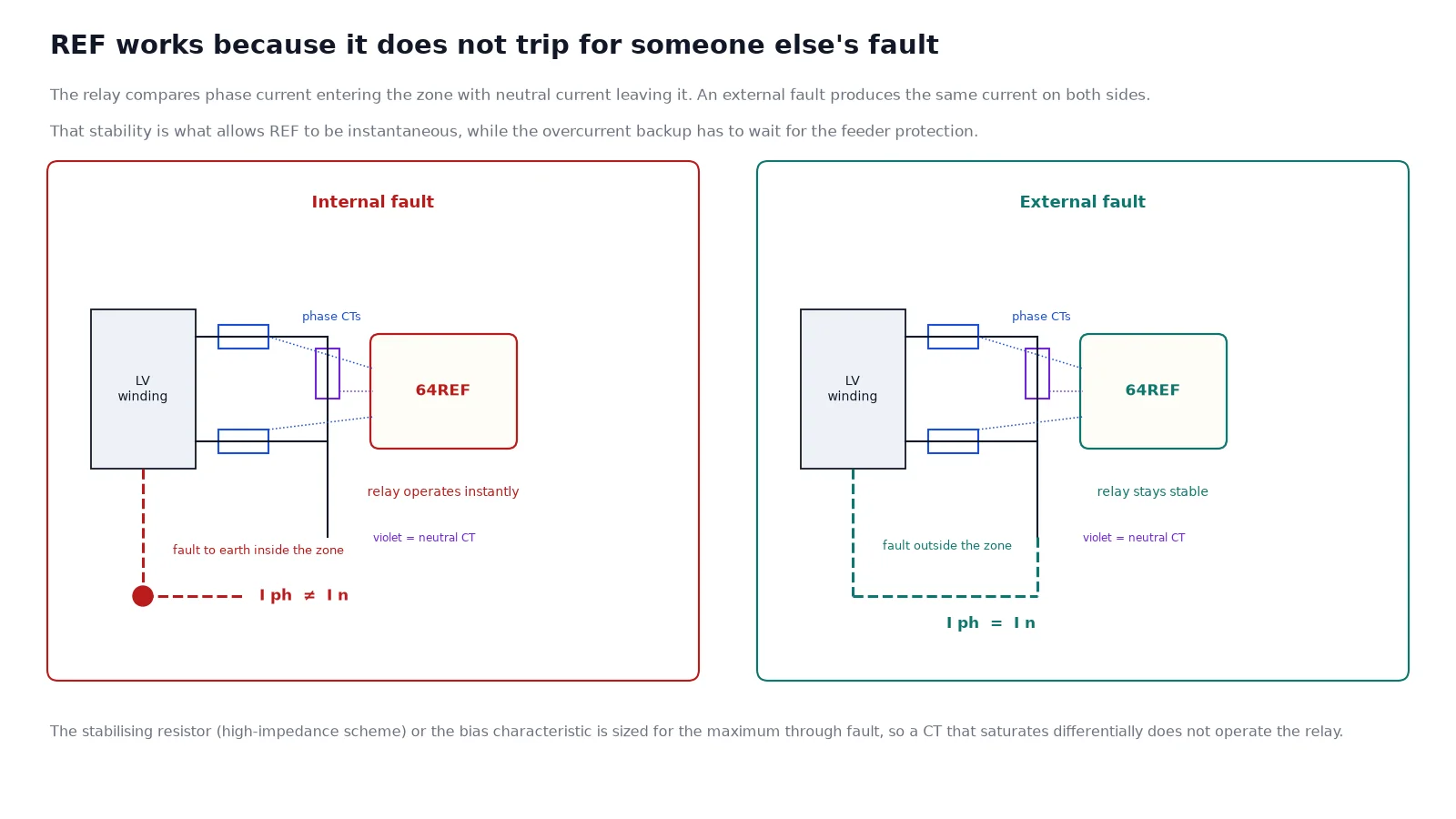
The scheme is most valuable on the part of the winding near the neutral, where a fault produces very little current and an overcurrent relay would take far too long. On a large LV winding with a resistance-earthed neutral, that zone is where a developing insulation fault sits quietly for months. High-impedance REF uses a stabilising resistor and requires matched CT ratios and a knee-point voltage high enough that the CTs do not saturate differentially during an external fault; a biased differential relay achieves the same result with settings rather than a resistor.
A standby earth fault element on a solidly earthed LV board is normally set at 10–20% of the transformer rated current, with a definite time delay of 0.2–0.5 s. The delay is there to let the outgoing feeder protection clear a fault on its own circuit first; if the fault persists, the standby element assumes it is on the busbar or in the transformer and trips. Setting it faster creates nuisance trips on downstream faults; setting it slower lets a busbar fault burn for longer than the switchgear withstand.
On a resistance-earthed system the pickup is set below the resistor current — commonly 10–20% of it — so that a partial fault, which produces less than the full resistor current, is still detected. The time delay can be shorter, because the reduced fault current limits the damage rate. In both cases the trip must go to the LV main breaker, with a backup trip to the HV breaker through a separate path so that a failed LV breaker does not leave the fault fed.
| Element | Typical pickup | Typical delay | Trip target |
|---|---|---|---|
| 51G standby, solidly earthed | 10–20% In | 0.2–0.5 s | LV main breaker |
| 51G, resistance earthed | 10–20% of resistor current | 0.1–0.3 s | LV main breaker |
| 64REF | 5–10% of winding rating | Instantaneous | HV and LV breakers |
| 50G on a feeder CBCT | 0.5–2 A primary | Instantaneous or 0.1 s | Feeder breaker |
Primary injection through the neutral earthing conductor is the only test that proves the whole chain: CT polarity, relay input mapping, setting group, trip output and breaker mechanism. It is also the test that finds reversed CT orientation, which is common and completely invisible to secondary injection. For core-balance CTs, the equivalent test injects current through a temporary conductor threaded through the window and confirms the relay sees the expected value with all phase conductors in place.
A stability test follows: inject or simulate a through fault that should not operate the REF, and confirm the relay stays stable. Finally, check the trip matrix in the actual relay configuration rather than in the design document — a correct scheme with a misconfigured output matrix trips the wrong breaker, and the mistake only appears during a real fault. The test sequence for the CTs themselves is in instrument transformer testing, and the ratio selection logic in the CT ratio selection table.
A Dyn transformer blocks zero-sequence current from reaching the HV side, so an LV earth fault has to be detected on the LV side and has to trip the LV breaker. Use a neutral CT for standby earth fault on solidly earthed boards, a core-balance CT where the current is deliberately limited, and REF where the winding near the neutral needs fast coverage. Do not rely on the residual connection of three phase CTs for sensitivity, and do not assume the CT ratio should follow the transformer rating — it should follow the fault current range. The current transformers for these schemes are in current transformers, and the wider distribution context is in transformers for commercial buildings.
No, not through a zero-sequence element, because the delta winding blocks the zero-sequence component. Only the phase overcurrent elements on the HV side see it, and they respond slowly and insensitively to a current that may be small in per-unit terms.
Both are earth fault overcurrent elements. 51N usually refers to a neutral current element measured by a dedicated neutral CT, and 51G to a general earth fault element that may be measured by a core-balance CT. The designation practice varies by relay manufacturer, so the single-line diagram should state the measurement point.
Most often because of unbalanced single-phase load and triplen harmonic current in the neutral, combined with CT ratio and phase errors. Raise the setting above the measured unbalance, add harmonic filtering, or replace the residual connection with a neutral CT.
Yes on a four-wire system. If the neutral bypasses the window, the vector sum is no longer zero under balanced load and the relay sees a permanent residual current.
Typically 5–10% of the winding rating, which on a 1 000 kVA LV winding is a few hundred amps — far more sensitive than the phase overcurrent protection, and fast enough to limit damage near the neutral.
An earth fault then produces only capacitive current, so overcurrent elements cannot detect it. Insulation monitoring, or a very sensitive core-balance scheme, is needed instead.