Most oil-immersed transformers do not fail from a component that wore out. They fail because a test that would have shown the problem was never run, or was run and the result was filed without being read. A transformer maintenance schedule is worth building for one reason: it converts a unit that will fail without warning into a unit that announces its condition months in advance, in numbers.
This schedule is written for distribution and small power transformers in the 11 kV to 36 kV range, the oil-immersed units that carry most of the world’s load and receive least of its attention. It assumes the oil is mineral, the cooling is ONAN or ONAF, and the tap changer is either a de-energised off-circuit type or a small on-load type.
What the schedule is actually for
Four things degrade in service, and each has a test that sees it before it becomes a failure.
- The oil itself — oxidation, moisture ingress, particulate. Seen by breakdown voltage, acidity and interfacial tension.
- The paper — thermal ageing, which is irreversible and determines the life of the unit. Seen by furan analysis and, indirectly, by carbon oxides in DGA.
- The active part — hot spots, arcing, partial discharge. Seen by dissolved gas analysis.
- The accessories — bushings, breather, gaskets, cooling fans, tap changer contacts. Seen by inspection, thermography and contact resistance.
The schedule exists to put the right test against the right mechanism at the right interval, not to run every test every year. Sampling a healthy 630 kVA unit quarterly is waste; sampling a 30-year-old 10 MVA unit annually is negligence.
The four oil tests that matter
Baseline chemistry is four measurements. The acceptance values below follow IEC 60422, which bands in-service oil by the highest voltage of the equipment rather than applying one pass mark to everything.
| Test |
Below 72.5 kV |
72.5–170 kV |
Above 170 kV |
| Breakdown voltage (BDV), kV |
40 or more good; 30–40 fair; under 30 poor |
50 or more good; 40–50 fair; under 40 poor |
60 or more good; 50–60 fair; under 50 poor |
| Water content, mg/kg |
30 maximum |
20 maximum |
15 maximum |
| Acidity, mg KOH/g |
0.30 maximum |
0.20 maximum |
0.15 maximum |
| Interfacial tension, mN/m |
18 minimum |
24 minimum |
32 minimum |
Two of these are consistently misread. Breakdown voltage is not a health score: it collapses only when there is free water or visible particulate, so a unit can be at 65 kV with paper that is thirty years into its life. Interfacial tension is the better early indicator, because it falls as polar oxidation products form, long before acidity moves and long before sludge appears. A unit whose IFT has dropped from 40 to 26 mN/m is oxidising, even if every other number is inside its limit.
For reference, oil after filling in new equipment should sit at acidity 0.03 mg KOH/g or below, IFT 35 mN/m or above, water below 20 mg/kg (below 10 above 72.5 kV) and BDV above 55 kV. If a two-year-old unit is already outside the new-oil window, the question is where the moisture or the oxygen is coming from.
DGA: the test that finds the fault first
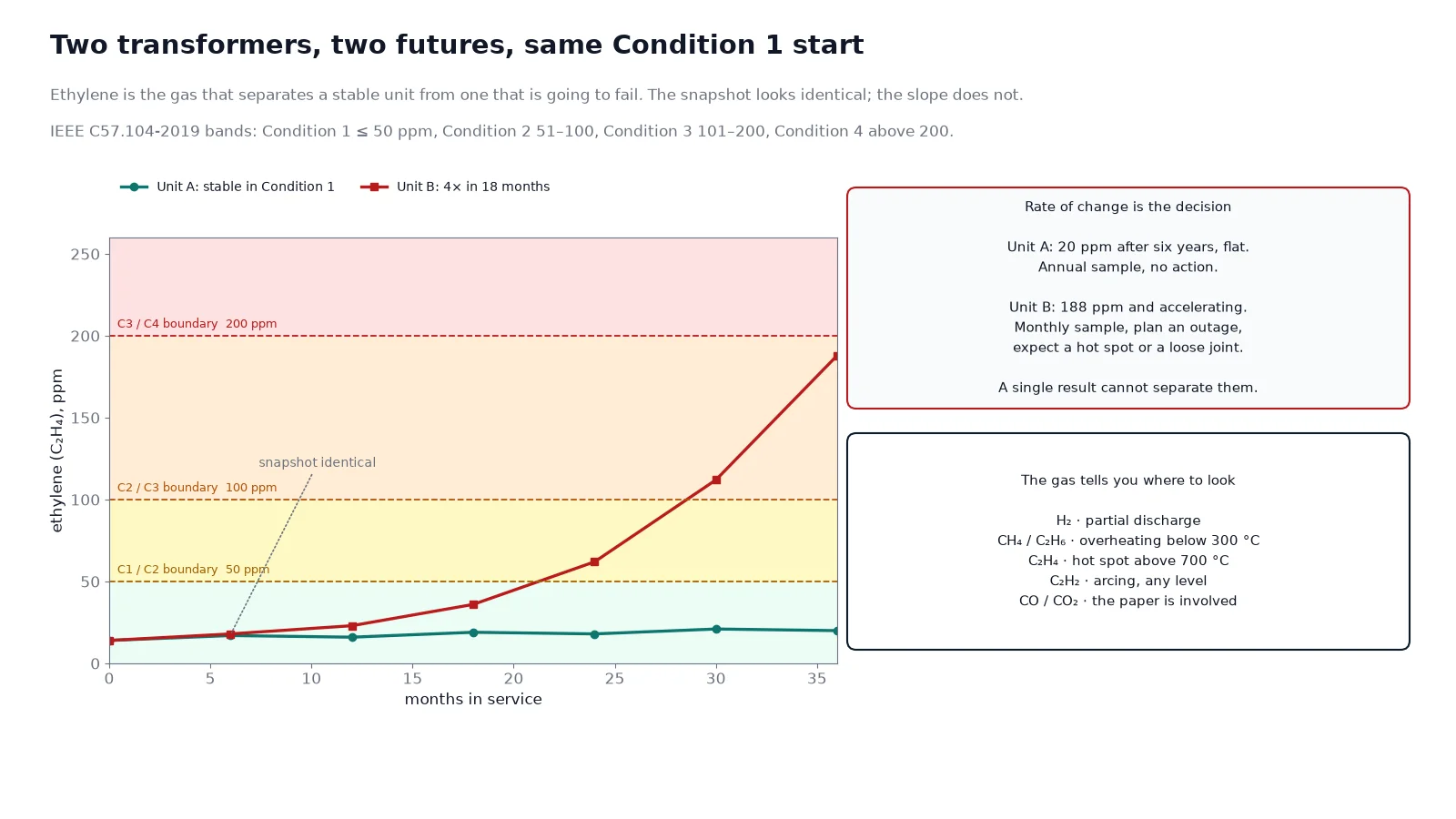
Dissolved gas analysis is the only routine test that identifies a developing fault by type and severity while the transformer is still in service. The gases and what they indicate are well established: hydrogen for partial discharge, methane and ethane for low-temperature overheating, ethylene for hot spots above roughly 700 °C, acetylene for arcing, and carbon monoxide and dioxide when the paper is involved.
IEEE C57.104-2019 gives the four condition bands. The change that matters most in that edition is acetylene: the Condition 1 limit came down from 35 ppm to 1 ppm, because acetylene only forms at arc temperatures and its presence at any concentration means arcing, not warming. Plenty of maintenance procedures in circulation still quote the older figure.
| Gas |
Condition 1 (normal) |
Condition 2 (caution) |
Condition 3 (alert) |
Condition 4 (act) |
| Hydrogen, ppm |
100 or less |
101–700 |
701–1,800 |
above 1,800 |
| Acetylene, ppm |
1 or less |
2–9 |
10–35 |
above 35 |
| Ethylene, ppm |
50 or less |
51–100 |
101–200 |
above 200 |
| Total dissolved combustible gas, ppm |
720 or less |
721–1,920 |
1,921–4,630 |
above 4,630 |
Use the trend, not the snapshot. A unit sitting stable in Condition 2 for four years is a different asset from one that crossed from 40 to 190 ppm ethylene in six months. Rate of change is the number to put in the log; reading a DGA report properly means reading three samples as a curve, not one as a verdict.
Silica gel, oil level and the conservator
The breather is the cheapest component on the transformer and the one that lets moisture into the paper. Colour-indicating silica gel shifts as it saturates; replace or regenerate it when roughly half to two thirds of the beads have changed colour, and check the oil seal at the bottom of the breather at the same time — an empty seal means the transformer has been breathing unfiltered, humid air for however long it has been dry.
Oil level in the conservator should be checked against the temperature-corrected gauge, not against the sight glass alone. A rising level without a temperature rise means gas is being generated; a falling level means a leak. Both are indications that deserve a sample, and neither is normal just because the transformer still works.
Gaskets are the usual leak path, and a weeping gasket is not cosmetic: it admits air and moisture while losing oil, and the two effects compound. Nitrile gaskets on a 20-year-old unit should be planned for replacement at the next outage, particularly at the radiator flanges and the bushing turrets where thermal cycling is greatest.
Bushings
Bushings account for a quarter of transformer failures in recent reliability surveys, and they are the component most often inspected visually and tested never. Three checks belong in the schedule.
- Thermography annually, under load, comparing phase-to-phase. A hot connection at the terminal is visible at 30 °C above its neighbours long before it fails.
- Power factor and capacitance at the five-to-six year interval for units above 72.5 kV, and at the ten-year mark for distribution voltages. A rising C1 power factor or a drifting capacitance means moisture or partial discharge inside the core.
- Visual at every inspection: chipped sheds, salt or cement dust deposits, cracks at the flange, oil weeping at the porcelain-to-metal joint, and the condition of the corona ring if one is fitted.
Cleaning is not cosmetic either. A contaminated bushing surface tracks at a fraction of its dry flashover voltage, which is why coastal and cement-plant installations need a cleaning interval rather than an inspection interval.
Tap changer
A de-energised tap changer that never moves will develop a resistive film on the contacts and fail on the day someone finally operates it. Exercise the full range and return to the service position once a year, with the transformer de-energised, and record the operating torque if the mechanism allows it.
On-load tap changers are a different regime. The diverter contacts wear, the compartment oil carbonises, and the motor drive is a mechanical system with its own maintenance. Sample the OLTC compartment separately from the main tank — mixing the two test results is a common reporting error, and the compartment oil will always look worse. Contact wear and oil condition together decide the overhaul interval; consult the manufacturer’s operation count rather than a calendar. The difference between the two families is covered in more detail in our note on OLTC and off-circuit tap changers.
Cooling system and thermal imaging
An ONAN unit has no fans to fail, which is one reason distribution transformers survive neglect. Once fans or pumps are fitted, they become the most likely cause of a derated unit: a failed fan stage is invisible unless the winding temperature is compared against load, and the transformer will simply run hotter for years.
Two checks catch it. First, verify that every fan stage starts at its set point — a thermocouple and a heat gun on the radiator are enough. Second, compare top-oil temperature rise against load against the commissioning baseline; a 5 K drift at the same load is a cooling problem, not a load problem. The cooling class designations and their failure modes are set out in our guide to ONAN and ONAF cooling.
Interval table
| Activity |
Distribution unit, under 2.5 MVA |
Power unit, above 2.5 MVA |
| Visual inspection and oil level |
6 months |
3 months |
| Infrared scan under load |
Annual |
6 months |
| Oil BDV, water, acidity, IFT |
2 years (annual after year 15) |
Annual |
| DGA |
2 years, annual if any gas is rising |
Annual, 6 months once Condition 2 is reached |
| Furan analysis |
At year 15 and every 3 years after |
Every 2 years from commissioning |
| Bushing power factor and capacitance |
10 years |
6 years |
| Tap changer exercise |
Annual |
Annual, plus OLTC oil per operation count |
| Gasket and seal inspection |
At each oil sample |
At each oil sample |
| Full electrical test set (IR, PI, ratio, winding resistance) |
5 years |
3 years |
Compress every interval by half when the unit runs above 80 % load continuously, sits in an ambient above 40 °C, or serves a load with significant harmonic content. Those three conditions age insulation faster than the calendar does, and a schedule built on years alone will lag the actual degradation. The baseline electrical test set is the same one used at handover; our factory acceptance test guide lists the values and how to interpret them.
Turning results into an action
Test results only pay for themselves when each band maps to a decision. Which band points to which mechanism inside the tank is set out in our analysis of the causes behind most transformer failures.
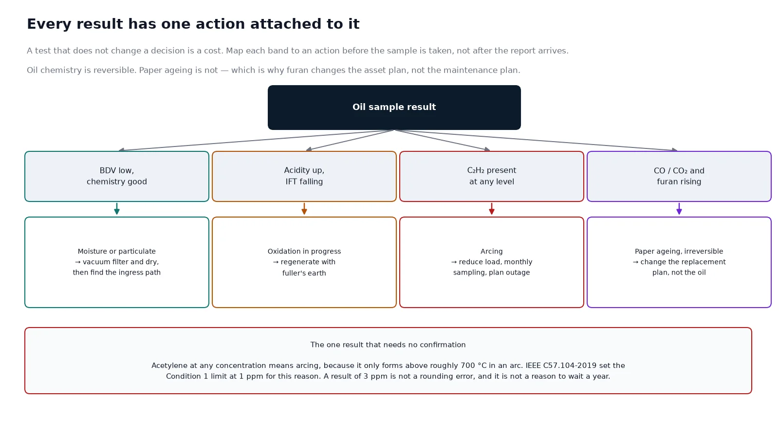
- BDV low, chemistry good. Moisture or particulate. Vacuum filter and dry the oil, then retest. If BDV recovers, find the ingress path.
- Acidity rising, IFT falling, BDV still acceptable. Oxidation in progress. Regenerate with fuller’s earth rather than replacing the oil, which also removes the degradation products that would otherwise contaminate the fresh charge.
- Acetylene present at any level. Arcing. Reduce load, increase sampling to monthly, and plan an outage. Do not wait for the next annual sample.
- Ethylene rising with stable other gases. A hot spot. Check cooling, check load, check for a loose connection; a winding resistance test will usually localise it.
- Carbon oxides rising with furans. The paper is ageing. This is the one result that cannot be reversed — it changes the asset plan, not the maintenance plan.
If the unit is a dry-type design, the schedule is different: there is no oil to sample, and condition monitoring leans on partial discharge, thermography and cleaning. Our note on maintaining a dry-type transformer covers that route. If you are still choosing between the two families for a new installation, the selection logic sits in our guide to selecting an oil-immersed transformer type, and the common ratings are listed on the oil-immersed distribution transformer page.
Frequently asked questions
How often should transformer oil be tested?
Every two years for a distribution transformer, annually for a power transformer above roughly 2.5 MVA, and annually from new for any unit above 15 years old. Once DGA reaches Condition 2, drop to six months; once acetylene appears at all, go to monthly until the cause is found.
What is a good BDV for transformer oil?
For equipment below 72.5 kV, 40 kV or above is good, 30–40 kV is fair and below 30 kV is poor under IEC 60422. For 72.5–170 kV the good band starts at 50 kV, and above 170 kV at 60 kV. A single low result should be confirmed with a repeat sample before any action.
When should silica gel be replaced?
When roughly half to two thirds of the beads have changed colour, and at least annually in humid climates. Replace the oil in the seal cup at the same time — an empty seal admits unfiltered air and defeats the breather entirely.
Does low interfacial tension mean the oil must be replaced?
Not usually. Falling IFT means oxidation products are forming, and regeneration with fuller’s earth removes them and restores the value. Replacement is the last resort, needed when the oil is heavily sludged or when regeneration cannot restore acidity and IFT together.
Can DGA predict a transformer failure?
It can show that a fault is developing and roughly what kind, which is usually enough to schedule an outage before failure. It cannot tell you the remaining life of the paper — that is furan and degree of polymerisation analysis.
Is oil testing needed on a sealed transformer?
Yes. A sealed unit still ages, and the absence of a conservator removes one moisture path but not thermal degradation. Sealed units are often sampled less often because there is no gauge to check, which is precisely why they fail unexpectedly.
The takeaway
A maintenance schedule is not a list of tests. It is a decision table: each measurement has a band, each band has an action, and the trend decides urgency. If you can fund only one activity on an oil-immersed unit, fund oil sampling and read it against the previous two results — the oil carries evidence of nearly every fault mechanism inside the tank, and it costs less than an hour of a technician’s time per year.
If you are building a maintenance plan for a specific unit, send us the rating, the voltage class, the age and your last two oil reports. We will return an interval table matched to the asset and flag any result that should change the plan.