A power transformer is used wherever electricity has to change voltage at high power. In the grid it steps generator output up to transmission voltage, links networks at different voltage levels, and steps back down to the level a distribution network can accept. Outside the grid it does the same job at the service entrance of a data centre, a mine, a refinery, a metro line or a 2 000 kVA factory intake. Wherever a large block of power needs to move between two voltage levels, there is a power transformer doing it.
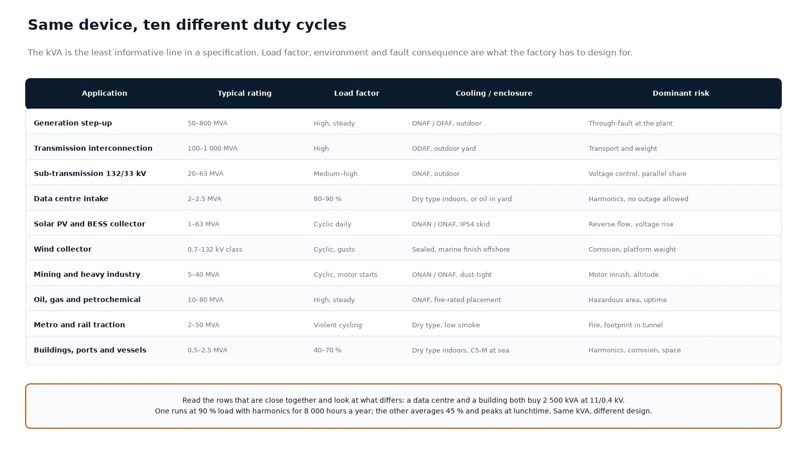
The useful way to answer the question is not a definition — it is a map. Almost every enquiry that reaches a transformer factory falls into one of ten applications, and the application, not the kVA, decides the cooling, the enclosure, the impedance, the tap range and the standard the unit is tested against. What follows is that map, with the technical consequences of each entry. For the underlying principle, how power transformers work covers the magnetism; this page covers the places you find them.
The short answer
A power transformer does three things, and every application is a version of one of them:
- Step up at a generator, so that power can travel long distances at a current low enough to keep line losses acceptable.
- Interconnect two networks that operate at different voltages, which is what a substation transformer does.
- Step down to a voltage that the next stage of the system, or the plant itself, can use.
The distinction from a distribution transformer is one of scale and role rather than principle. A distribution unit performs the final step down to 400/230 V at the point of use; a power transformer works between the high-voltage levels behind it. The boundary between the two and the numbers that shift across it are covered in power transformer vs distribution transformer.
The five places a power transformer sits in the grid
Follow one kilowatt from a generator to a factory and it passes through five transformation points. Everything else on the list below is a variation on one of them.
| Stage |
Typical transformation |
Typical rating |
What the design has to solve |
| Generator step-up |
10–25 kV to 110–400 kV |
50–800 MVA |
High current at the generator terminals, heavy through-fault duty, delta winding to block zero sequence |
| Transmission interconnection |
400/220 kV, 220/110 kV |
100–1 000 MVA |
Very high impedance, on-load tap changing, transport weight limits |
| Sub-transmission |
132/33 kV, 110/35 kV |
20–63 MVA |
Voltage control across a meshed network, parallel operation |
| Primary distribution |
33/11 kV, 35/10 kV |
5–20 MVA |
Fault level for the feeder switchgear, future load growth |
| Industrial or building intake |
33/11 kV, 11/6.6 kV, 11/0.4 kV |
1–40 MVA |
Motor starting inrush, harmonics, ambient and enclosure |
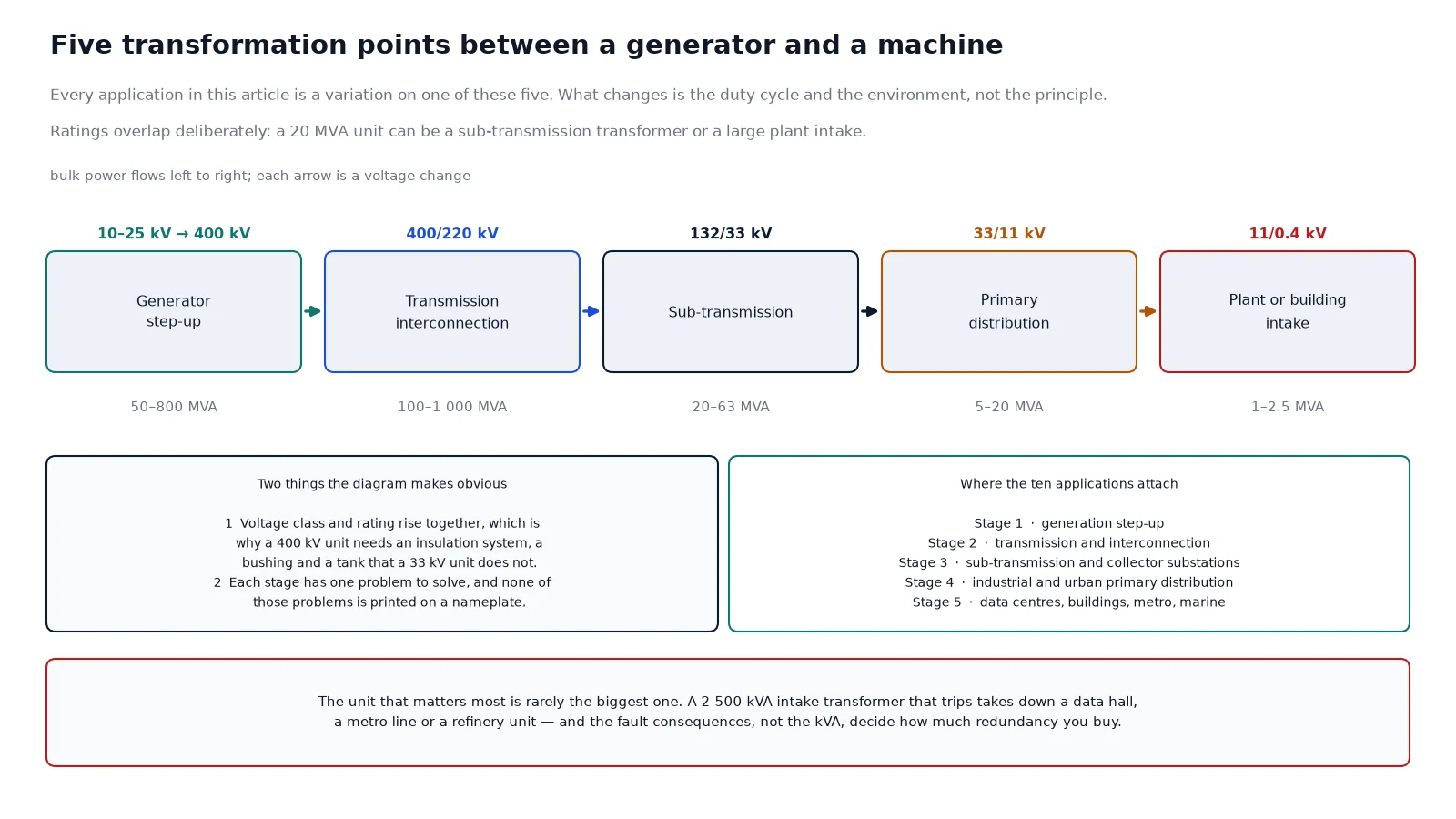
Two things are worth noticing in that table. The first is that voltage class and rating rise together, which is why the physical size of the equipment grows so steeply: a 400 kV unit has an insulation system, a bushing and a tank that a 33 kV unit simply does not need. The second is that every stage has a different problem to solve, and none of those problems is visible on a nameplate.
Ten applications in practice
1. Power generation, step-up
A generator produces at 10 to 25 kV because that is the practical limit of the machine’s insulation and slot design. Transmission at that voltage would lose most of the power over 200 km, so a step-up transformer at the plant output raises it to 110, 220 or 400 kV. The unit is sized to the generator, runs at high load factor, and is normally a three-phase oil-immersed unit with a delta-connected generator winding, forced cooling and a high short-circuit withstand because a fault close to the plant is the most severe case in the system.
2. Transmission substations and grid interconnection
Where two transmission networks meet, an autotransformer or a two-winding transformer links them and an on-load tap changer holds the secondary voltage while power flows in either direction. This is the application with the highest impedance values, the largest units and the longest lead times — 78 to 130 weeks is a normal range for a bespoke MV power transformer today, and more for the largest units. Transport is a design constraint as much as a logistic one: a unit that cannot move by road has to be designed to fit a rail gauge or built on site.
3. Sub-transmission and primary distribution substations
The 132/33 kV and 33/11 kV substations are where the transmission mindset meets the distribution one. Ratings are modest, redundancy matters more than efficiency, and the units usually run in parallel with a sibling, which fixes the impedance, ratio and vector group relationship. A pair that is not matched will not share load, and one unit will run hot while the other idles. This is the stage where a wrong impedance is most often discovered — after the LV switchgear has been ordered.
4. Data centres
A data centre is a load with three properties that shape the transformer: it is large, it is almost constant, and it cannot be interrupted. Utility supply arrives at 33 or 11 kV and is transformed to 415/400 V in unit substations of 2 to 2.5 MVA, usually in a 2N arrangement so that one unit and one feed can be taken out without dropping the hall. Load factor runs at 80 % to 90 %, which is far above what a distribution transformer is designed for, and the harmonic content from server power supplies pushes the design toward K-factor rating or derating. Dry type is common indoors for fire reasons; oil-immersed units sit in an outdoor yard. The data centre transformer guide covers the redundancy and heat-rejection side in more detail.
5. Solar PV and battery storage
An inverter delivers at 400 to 800 V, and a plant of 100 MW has hundreds of them. Inverter transformers step each block up to 33 kV, and a collector substation transformer takes 33 kV to 132 or 220 kV. The duty is unlike a transmission unit’s: output follows the sun, so the unit cycles daily, the power flow reverses at sunset, and the harmonic spectrum from the inverters is part of the design. On long feeders the tap has to be set for voltage rise, not voltage drop. Transformers for solar PV and BESS sets out the collector arrangement and the cycling duty.
6. Wind farms
Onshore, each turbine has a small step-up unit in the nacelle or the tower base, typically 0.69/33 kV, and a collector substation aggregates the strings to 132 kV or above. Offshore, all of that equipment sits on a platform, which changes the specification more than the electrical design: sealed enclosures, corrosion protection to a marine class, no routine oil handling, and weight that the platform structure has to carry. The transformer is also the component that decides how much of the turbine’s output the collector can accept on a gusty day.
7. Mining and heavy industry
A mine is a concentrated load in a place with no infrastructure. Supply arrives at 33 kV or 132 kV, is transformed to 11 kV or 6.6 kV for the distribution ring, and to 0.69 kV or 0.4 kV for the largest drives. The recurring technical problems are motor starting — a 5 MW mill motor can pull several times its rated current for seconds — frequent load cycling from crushers and hoists, abrasive dust, and altitude that reduces cooling. Mobile substations on skids or trailers are common because the pit moves. Transformers for mining covers the duty cycle and the harmonic load from variable-speed drives.
8. Oil, gas and petrochemical plants
Refineries and petrochemical plants transform 132 kV or 110 kV down to 33 kV and 11 kV, then to 6.6 kV or 0.69 kV for motors. Two features dominate the specification. First, continuity: a trip on the main transformer can shut a process unit for days, so redundancy and fast protection are worth more than first cost. Second, the environment: classified areas require equipment with no arcing contacts, and units adjacent to process areas need fire protection and blast-resistant placement. Where space is tight, dry type units replace oil-immersed units for the lower ratings. Power transformers for oil and gas covers the hazardous-area and reliability requirements.
9. Metro, rail and tunnelling
A metro line is a chain of small substations. Traction substations take 33 kV or 110 kV from the utility and feed rectifier transformers that deliver 590 V or 1 180 V to produce 750 V or 1 500 V DC on the third rail. Auxiliary transformers supply 400 V for lighting, ventilation, escalators and signalling. Everything is underground, so fire performance, low smoke emission and a footprint that fits a tunnel recess matter as much as efficiency, and the load is violently cyclic: a train accelerating draws several MW for 20 seconds and then nothing. Transformers for metro and tunnel substations covers the traction duty and the ventilation consequences.
10. Commercial buildings, EV charging hubs, ports and vessels
The last group is the non-utility end user. A high-rise or a shopping centre takes 11 or 33 kV and transforms to 400 V in units of 1 000 to 2 500 kVA, dry type because the plant room is inside the building, and sized for harmonic loads from lifts, chillers and IT. An EV charging hub is the same arrangement with a worse load profile: chargers switch on in blocks, the harmonic spectrum is wide, and the transformer sees a load that steps rather than ramps. Ports and vessels add corrosion and shore-power conversion, where a 6.6 kV or 11 kV supply has to be transformed and matched in frequency to the ship. Building and commercial transformers and marine and offshore transformers cover the two ends of that range.
What changes from one application to the next
The kVA is the least informative number in a specification. These six parameters are what actually differ, and they differ far more between applications than between ratings.
| Parameter |
Set by |
Typical spread across applications |
| Load factor |
Duty cycle |
40 % for a building, 90 % for a data centre, cyclic for traction and solar |
| Cooling |
Ambient and enclosure |
ONAN sealed indoors to ODAF in a transmission yard; derating above 40 °C or 1 000 m |
| Enclosure and finish |
Environment |
IP21 in a plant room, IP44 outdoors, IP56 with C5-M finish on a weather deck |
| Impedance |
Downstream fault rating |
4 % at a building intake to 20 % at a transmission interconnection |
| Tap range |
Whether the source voltage moves |
Off-circuit ±2 × 2.5 % on a distribution unit, on-load ±8 × 1.25 % at a substation |
| Protection devices |
Consequence of failure |
Fuses and a temperature relay on a small unit, Buchholz and differential on a large one |
How to specify from the application, not the label
Five questions, asked in this order, will produce a specification that a factory can quote without guessing:
- What is the source voltage and how much does it move? That decides the tap range and whether an on-load tap changer is justified.
- What is the peak load, and the average over 24 hours? Peak sets the rating; average sets the loss balance and therefore the design point.
- What is the fault level the equipment downstream can survive? Work back to an impedance, then check the voltage drop at that impedance and full load.
- Where does the unit physically stand? Indoors or outdoors, ambient temperature, altitude, dust, salt, flood risk and available footprint all change the enclosure and the cooling.
- What happens to the process if this unit trips? The answer decides redundancy, protection class and whether dry type is worth the extra cost.
Answer those and the type code, the impedance band and the cooling class follow. Skipping them is how projects end up with a compliant unit that does not fit the room, or a unit that shares load badly with its twin. The transformer product range covers the 11 to 40.5 kV classes where most of these applications land.
Conclusion
A power transformer is used at every point where a large block of power changes voltage: at the generator, between transmission networks, at the substation that feeds a city, and at the intake of any plant large enough to need its own supply. The ten applications above account for almost all of that demand, and they differ from each other in duty cycle, environment and fault consequence rather than in principle.
If you are specifying one, start from the application and the load profile and let the rating follow. Send the source and load voltage, the peak and average load, the fault level downstream, and where the unit will stand — with those four answers a factory can propose an impedance, a cooling class and an enclosure that will actually work on site.
FAQ
Where are power transformers used in everyday life?
Everywhere electricity is delivered in bulk. The substation at the edge of a town that steps 132 kV down to 33 kV contains power transformers, and so does the unit that feeds a shopping centre, a metro line or a hospital. The device on the pole outside a house is a distribution transformer; the equipment that makes the pole supply possible is not.
What is the difference between a power transformer and a distribution transformer in use?
The power transformer works between high-voltage networks and is loaded near its rating continuously. The distribution transformer works at the end of the chain, stepping medium voltage down to 400/230 V, and is loaded at 40 % to 60 % of rating on average. The application decides the impedance, the tap changer and the cooling, and those are what actually differ.
Can a power transformer be used for distribution?
Electrically yes, and it happens at industrial sites where a 10 MVA 33/11 kV unit feeds a plant distribution ring. Commercially it is usually the wrong choice: the unit is built for a duty cycle and a fault level it will never see, and the buyer pays for an on-load tap changer and an impedance that the plant does not need.
What rating do most industrial applications need?
Most sit between 1 MVA and 40 MVA. A factory intake is commonly 1 000 to 2 500 kVA at 11/0.4 kV, a plant distribution transformer 5 to 20 MVA at 33/11 kV, and a dedicated substation for a large site 20 to 63 MVA at 132/33 kV. Above that, the application is normally a utility or a generation project.
Why do data centres and metro lines use different transformers for the same kVA?
Because the duty and the environment differ. A data centre unit runs at a high, steady load indoors and has to tolerate harmonics without overheating, so it is often dry type with K-factor rating. A traction unit feeds a rectifier, sees a load that switches on and off in blocks, and sits in a tunnel where fire performance and footprint dominate. Same kVA, different specification.
Do wind and solar projects use power transformers or distribution transformers?
Both, at different points. Each inverter or turbine has a small step-up unit in the distribution band, and the collector substation that aggregates the plant uses power transformers from 33 kV to 132 kV or above. The collector unit is where the cycling duty and the harmonic spectrum of the inverters have to be designed for.