An oil and gas power transformer is less a product category than a set of constraints applied to an ordinary distribution or power transformer. A refinery does not buy a transformer because it says “oil and gas” on the datasheet. It buys a transformer that will still be in service after fifteen years of continuous load, harmonic-rich current from variable frequency drives, a salt-and-H2S atmosphere, and a plant turnaround schedule that allows no unplanned outage.
That is why the specification for these units diverges so quickly from a standard building transformer. Offshore platforms pay for weight and footprint. Refineries pay for fire separation and spare capacity. Pipeline compressor stations pay for wide ambient range and remote monitoring. All three pay for the same underlying discipline: the transformer has to be specified against the process, not against a nameplate template.
This guide works through where these units sit on the single-line, how hazardous area classification changes siting, how drive harmonics force derating, and what to put in the specification so that the bid you receive is comparable. Where a detail depends on the site’s own electrical specification, we say so rather than inventing a universal rule.
Quick answer: what makes an oil and gas transformer different
Four factors drive almost every departure from a standard specification:
- Continuous duty at high load factor. A refinery unit may run at 0.75 to 0.90 load factor for years. Loss evaluation, not first cost, dominates the lifecycle decision.
- Harmonic-rich load. Six-pulse drives inject 25 to 35 percent current distortion. The transformer must be specified with a K-factor or derated by calculation, not by guesswork.
- Hazardous area adjacency. The transformer is normally sited outside the classified zone, which sets distance, fire separation and sometimes pressurisation requirements.
- Corrosive and saline atmosphere. Coating systems, tank sealing and terminal arrangements follow corrosion-class practice rather than indoor-switchroom practice.
| Segment |
Typical transformer duty |
Dominant requirement |
Secondary driver |
| Upstream (wellhead, ESP, gathering) |
Small distribution units, 0.5 to 5 MVA |
Wide ambient, sand and dust ingress |
Remote monitoring, minimal maintenance visits |
| Midstream (pipeline compressor and pump stations) |
2 to 30 MVA, often with large VFD loads |
Harmonic derating, voltage regulation |
Load step tolerance, soft-start interaction |
| Downstream (refinery, petrochemical) |
10 to 60 MVA main units plus 1 to 5 MVA distribution |
Fire separation, N-1 redundancy, spare capacity |
Through-fault strength, DGA monitoring |
| Offshore platform / FPSO |
1 to 40 MVA, weight-critical |
Footprint and mass, marine certification |
Seismic and dynamic loads, corrosion class |
Where the transformer sits on the refinery single-line
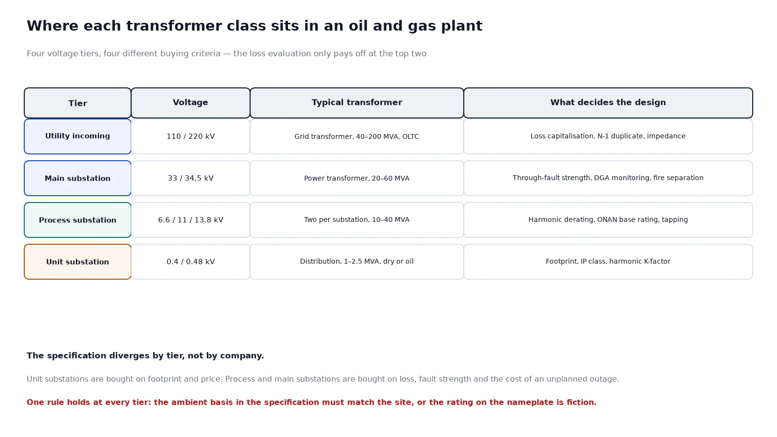
Most petrochemical plants use three or four voltage tiers. A typical configuration runs a utility incoming at 110 or 220 kV, steps down to 34.5 or 33 kV at the main substation, distributes at 13.8 or 11 kV to process substations, and then steps down again to 6.6 or 4.16 kV for large motors and 480 or 400 V for low-voltage boards.
The transformers at each tier are different machines with different economics:
- Main incoming / grid transformers. High voltage, high impedance, often with on-load tap changers and duplicate units. Loss capitalisation is usually mandatory in the evaluation.
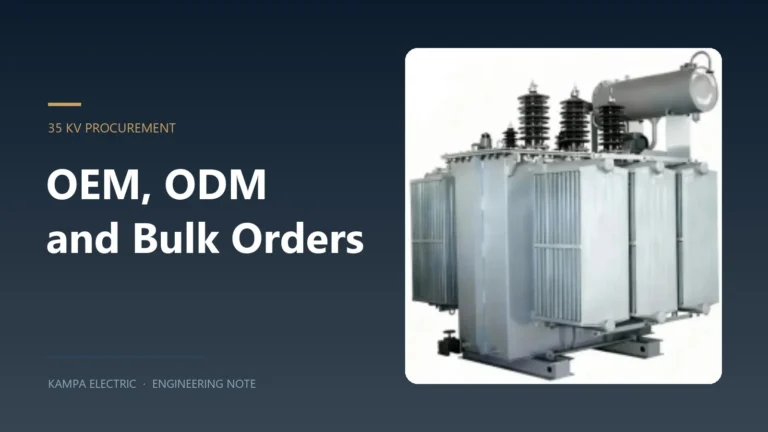
- Process substation transformers. 33/13.8 kV or 34.5/6.6 kV, 10 to 40 MVA, frequently two per substation so that one can be maintained while the other carries the process.
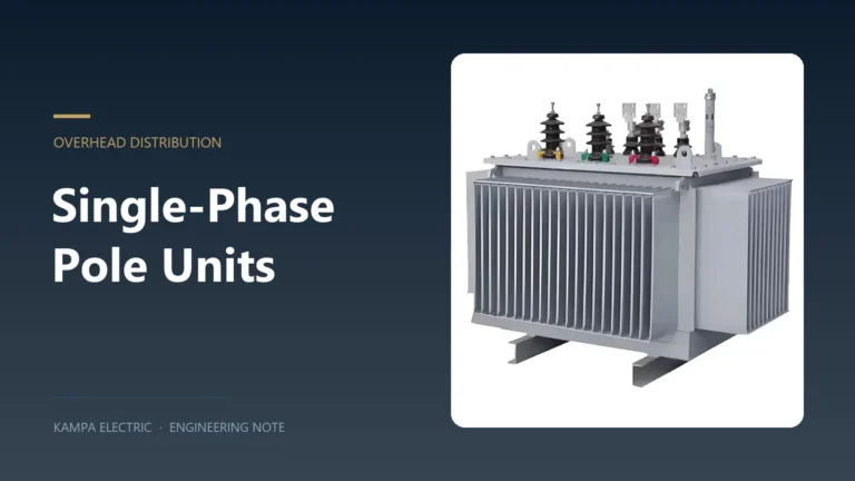
- Unit substation transformers. 13.8/0.48 kV or 11/0.4 kV, 1 to 2.5 MVA, dry-type in the switchroom or oil-immersed outdoors.
- Special-duty units. Rectifier transformers for electrolysis, furnace transformers, VFD interface transformers with extended delta or shielding.
If your project is at the distribution end of that list rather than the main-incoming end, compare the options on the oil immersed power transformer range before finalising the dielectric and cooling basis, because the cost slope between a standard distribution unit and a power-class unit is steep.
Hazardous area classification and transformer siting
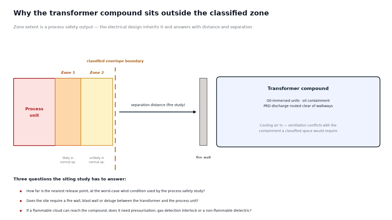
This is where oil and gas projects most often diverge from a generic specification. Process areas are classified into zones by the probability of a flammable atmosphere being present. The transformer itself is almost never installed inside a classified zone, because both the oil and the tap changer are potential ignition sources and because the ventilation required to keep the tank cool conflicts with the containment required for a classified space.
What changes instead is distance and separation. The electrical building or transformer compound is pushed to the edge of the classified envelope, and the design then has to answer three questions:
- How far is the nearest classified release point, and what is the zone extent under the worst-case wind condition used by the process safety study?
- Does the site require a fire wall, blast wall or deluge between the transformer and the process unit?
- If the transformer is close enough to be affected by a flammable cloud, does it need positive pressurisation, gas detection interlock, or a non-flammable dielectric?
Zone extent is a process safety output, not an electrical one. It should come to you as a drawing with the classification and the release points marked. If a vendor quotes a transformer without asking for that drawing, the quote is not yet a design.
Why dry-type does not automatically solve the problem
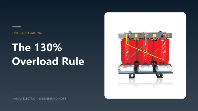
A common assumption is that a cast-resin dry-type transformer removes the fire risk and therefore removes the siting constraint. It removes the oil pool fire, which is real value. It does not remove the arc-fault energy inside the enclosure, it does not remove the surface temperature question, and it does not remove the need to keep the unit out of a zone where a flammable cloud can form. For 33 kV and above, the thermal and cost economics also move against cast resin. Treat dry-type as a fire-load reduction measure, not as a hazardous-area exemption.
Drive harmonics: specifying for the load, not the nameplate
Refineries and pipelines are full of variable frequency drives. A six-pulse drive produces a current waveform with strong fifth and seventh harmonics, and those harmonic currents cause additional winding eddy-current loss and stray loss in the transformer. The result is a hot spot that the nameplate temperature rise never predicted.
Two routes exist, and they are not interchangeable:
| Route |
How it works |
When to use it |
What to state in the specification |
| K-factor rated unit |
Winding and core designed for a defined harmonic spectrum; UL K-4, K-9, K-13, K-20 classes |
Known drive population, North American practice, dry-type units |
K-factor plus the assumed harmonic spectrum and the load profile behind it |
| Calculated derating |
Losses computed for the actual spectrum; the unit is oversized until the hot spot is back inside its insulation class |
Large units, mixed load, IEC practice |
Harmonic spectrum, per-order current distortion, expected coincident demand |
| Drive-isolating transformer |
Dedicated transformer per drive group, often with extended delta or shielding for 18-pulse arrangements |
Very large drives, 12-pulse or 18-pulse front ends |
Pulse number, phase shift, impedance, winding configuration |
Whichever route is chosen, put the harmonic study in the annex. A K-13 label on a nameplate with no spectrum behind it is a marketing claim, not an engineering basis.
Cooling class: the selection that decides footprint and life
Oil-immersed units in oil and gas service are usually specified with a two- or three-stage cooling class so that capacity can be recovered if a fan bank fails. ONAN alone leaves you with no reserve. ONAN/ONAF adds roughly 15 to 25 percent capacity with fans running, at the cost of fan power, noise and one more thing to maintain. OFAF or ODAF is used where the footprint must be held, but it adds pumps and oil flow monitoring.
The operational question is not which class is more efficient. It is what the plant does when the fans stop. If the process can be held at reduced throughput on ONAN rating, the fan failure is an alarm. If the process cannot be held, the fan failure is a trip. That distinction should be written into the specification as the required ONAN base rating, and the cooling classes discussed in detail in our guide to transformer cooling classes ONAN and ONAF apply directly here.
Ambient basis
Gulf and tropical sites regularly see 50 degrees Celsius shade temperature with solar gain on the tank, while a Siberian or Central Asian compressor station can see minus 45 degrees Celsius. Both ends matter. The hot end sets the rating; the cold end sets the oil type, the gasket material and the tap changer mechanism. A transformer rated at 40 degrees Celsius ambient and installed at a 50 degree site is a derated transformer, whatever the nameplate says.
Corrosion, sealing and the atmosphere question
Refinery and coastal atmospheres combine moisture, chloride and in some cases hydrogen sulphide. Three specification items carry most of the weight:
- Coating system. For coastal or C5-class exposure, the paint system should be a documented multi-coat system with a stated total dry film thickness, not a colour reference. Ask for the system sheet, not the colour chip.
- Tank sealing and breathing. A hermetically sealed tank removes oil-to-air contact and is the strongest answer to humid and saline air. Where a conservator is required, the breather and silica gel arrangement becomes a maintenance item that must be in the site’s routine.
- Terminal and cable box design. Cable boxes, bushings and marshalling boxes are where corrosion first shows. Specify the enclosure protection and the material, and check that the cable entry direction matches the actual trench or tray layout.
For units destined for export markets with mandatory certification, the documentation chain is a parallel workstream. Our breakdown of transformer certification for export covers which schemes actually apply above 1 kV and why CE marking does not.
Fire safety: the dielectric decision
Mineral oil has a flash point around 145 degrees Celsius. Natural and synthetic ester dielectrics have flash points above 300 degrees Celsius and, in the case of ester, a much higher fire point and a measurable self-extinguishing tendency. That does not make an ester-filled transformer fireproof, and it does not remove the need for separation. It does change the fire-load calculation and, on some sites, the separation distance that the fire study requires.
Three practical positions exist, and they are priced very differently:
- Mineral oil with separation. The default. Fire wall or separation distance, oil containment, and a deluge or spray system if the site’s fire philosophy requires it.
- Ester-filled. Higher first cost, reduced separation requirement, better performance under overload because of the higher flash and fire point, and biodegradable if spilled. Increasingly common on offshore and environmentally sensitive sites.
- Dry-type. No oil at all, appropriate up to about 36 kV. Restricted by cost and by the practical size limit of cast resin above that voltage.
Decide this early. Changing dielectric after the layout is frozen reopens the fire study, the separation drawing and often the civil design.
Protection and monitoring: what to insist on
A transformer in a process plant is usually unmanned for most of its life. The monitoring package is therefore part of the specification, not an accessory.
| Device |
What it catches |
Notes for oil and gas duty |
| Winding temperature indicator with alarm and trip |
Overload and cooling degradation |
Simulate the trip contact during FAT; a WTI that cannot trip is a gauge |
| Oil temperature indicator |
Cooling system failure, blocked radiators |
Confirm the alarm setpoints against the plant philosophy, not the factory default |
| Buchholz relay (conservator types) |
Internal arcing, gas generation, oil loss |
Requires a conservator; sealed tanks use pressure devices instead |
| Pressure relief device |
Rapid internal pressure rise |
Route the discharge away from walkways and process equipment |
| Sudden pressure relay |
Fast internal fault |
Commonly specified in addition to differential protection on larger units |
| Dissolved gas analysis sampling point |
Incipient faults over time |
A baseline DGA at the factory is worth more than the first site sample |
| Partial discharge measurement |
Insulation defects |
Insist on a recorded PD trace for the FAT, not a pass statement |
| Remote I/O for SCADA |
Everything above, at the control room |
Agree the protocol and the point list before the order, not at commissioning |
Specification checklist for an oil and gas transformer
Fifteen fields decide most of the technical and commercial outcome. If any of them is blank in your enquiry, every bid you receive will assume something different.
- Voltage ratio, winding connection and vector group, with the neutral arrangement stated.
- Rated power and the required ONAN base rating separate from the forced-cooled rating.
- Ambient basis: maximum, minimum and the daily average used for the rating calculation.
- Altitude, and whether any correction applies.
- Insulation levels: lightning impulse and power frequency withstand, stated in kV.
- Impedance and its tolerance, plus the fault level at the terminals.
- Tap range and tap type: off-circuit or on-load, number of positions, step size.
- Harmonic spectrum and K-factor or the agreed derating basis.
- Dielectric: mineral oil, natural ester, or dry-type, with the fire philosophy reference.
- Cooling class stages and the fan or pump redundancy requirement.
- Corrosion class, coating system and total dry film thickness.
- Enclosure protection for cable boxes and marshalling boxes, and cable entry arrangement.
- Monitoring and protection device list, with alarm and trip setpoints.
- Seismic or dynamic qualification requirement, if the site or the platform requires it.
- Documentation, inspection plan and the witness test points the buyer intends to attend.
Common mistakes on these projects
- Rating to 40 degrees ambient. The nameplate looks right and the unit runs hot for fifteen years.
- Ignoring the harmonic study until after the order. Derating is cheap at the design stage and expensive as a change order.
- Assuming dry-type removes the siting constraint. It reduces fire load; it does not create a hazardous-area exemption.
- Specifying a K-factor without a spectrum. The number becomes an unverifiable promise.
- One transformer where the process needs two. The maintenance question is asked nine months after commissioning, when the answer is expensive.
- Leaving the neutral arrangement to the vendor. It decides protection settings, earthing design and cable sizing downstream.
Where to go next
For refinery distribution and unit substations in the 11 to 35 kV range, the practical starting point is the oil immersed distribution transformer specification, then a review of what changes when you move up to a power-class unit. If your project is a 33 or 35 kV substation, the selection logic in our 35 kV oil immersed transformer selection guide covers the impedance and tapping decisions that most often cause trouble.
For larger units with an on-load tap changer, the 35 kV oil immersed power distribution transformer range shows the current build configurations, and the plant-level context for protection and earthing sits in our industrial power distribution and protection material.
FAQ
Can an oil-immersed transformer be installed inside a hazardous area?
In practice, no. The oil, the tap changer and the venting arrangement are all potential ignition sources, and the cooling ventilation conflicts with the containment a classified space requires. The usual design places the transformer outside the classified envelope and manages distance, fire separation and cable routing from there. Any exception needs a formal risk assessment and the site’s own approval, not a vendor’s opinion.
What K-factor should I specify for a refinery transformer?
It depends on the drive population and the coincident demand, not on a rule of thumb. K-4 suits light drive content, K-13 is common where a significant share of load is six-pulse, and K-20 is for heavy drive-dominated boards. In IEC practice the same intent is achieved by calculated derating for the actual harmonic spectrum. Ask for the spectrum before you ask for the K number.
Is a hermetically sealed tank better than a conservator for coastal sites?
For corrosive and saline atmospheres, sealed tanks remove the oil-to-air breathing path and are usually the better default. The trade-off is that you lose the Buchholz relay, so protection shifts to pressure devices and differential protection. Where a conservator is required by the site standard, plan the silica gel and breather into the maintenance schedule from day one.
How much spare capacity should a process substation transformer carry?
Enough to carry the process at the reduced throughput the plant can tolerate on one transformer. That is a process decision expressed as a load figure. Sizing for a flat 50 percent spare without checking the actual process turndown usually produces an oversized transformer with worse part-load efficiency and a higher fault level.
Does natural ester oil change the loading capability?
Ester has a higher flash and fire point and better tolerance of overload temperature, which is why it is common on offshore and environmentally sensitive sites. It also has different viscosity and ageing behaviour, so the cooling design and the oil test regime must be adjusted with it. Do not simply substitute ester into a mineral-oil design without re-checking temperature rise.
What tests should be witnessed for an oil and gas project?
At minimum, ratio, winding resistance, impedance and load loss, no-load loss, applied and induced voltage, partial discharge, and oil tests before and after filling. On larger units, add temperature rise and impulse if they are type tests being repeated. Witness the calibration of the loss measuring instruments first, because a loss test on uncalibrated equipment is an opinion.
If you are comparing a standard distribution unit against a power-class unit for a process substation, send the voltage ratio, rated power, ambient basis and harmonic spectrum, and we will confirm which build actually fits rather than quoting the nearest catalogue item.