The difference between a power transformer and a distribution transformer is not a difference in how the two machines work. Both sit in the same magnetic circuit of the grid, both step alternating voltage up or down by the turns ratio, and both are built to IEC 60076 or IEEE C57.12. The difference is where the unit sits in the network, how much power passes through it, and how it is loaded over twenty-four hours. Every real design difference — impedance, tap range, cooling, loss balance, enclosure — follows from those three facts.
That matters because the two labels get used interchangeably in tenders, and a mislabelled unit is usually a mispriced one. A 10 MVA 33/11 kV unit is called a power transformer by one buyer and a distribution transformer by another, and the two buyers expect different impedances, different tap changers and different loss guarantees. This guide separates the label from the specification: what actually distinguishes the two categories, which numbers change, and how to select when your project falls into the overlap. If you only need the terminology of the wider family, the transformer types overview covers it; this page stays on the power transformer vs distribution transformer boundary itself.
The short answer
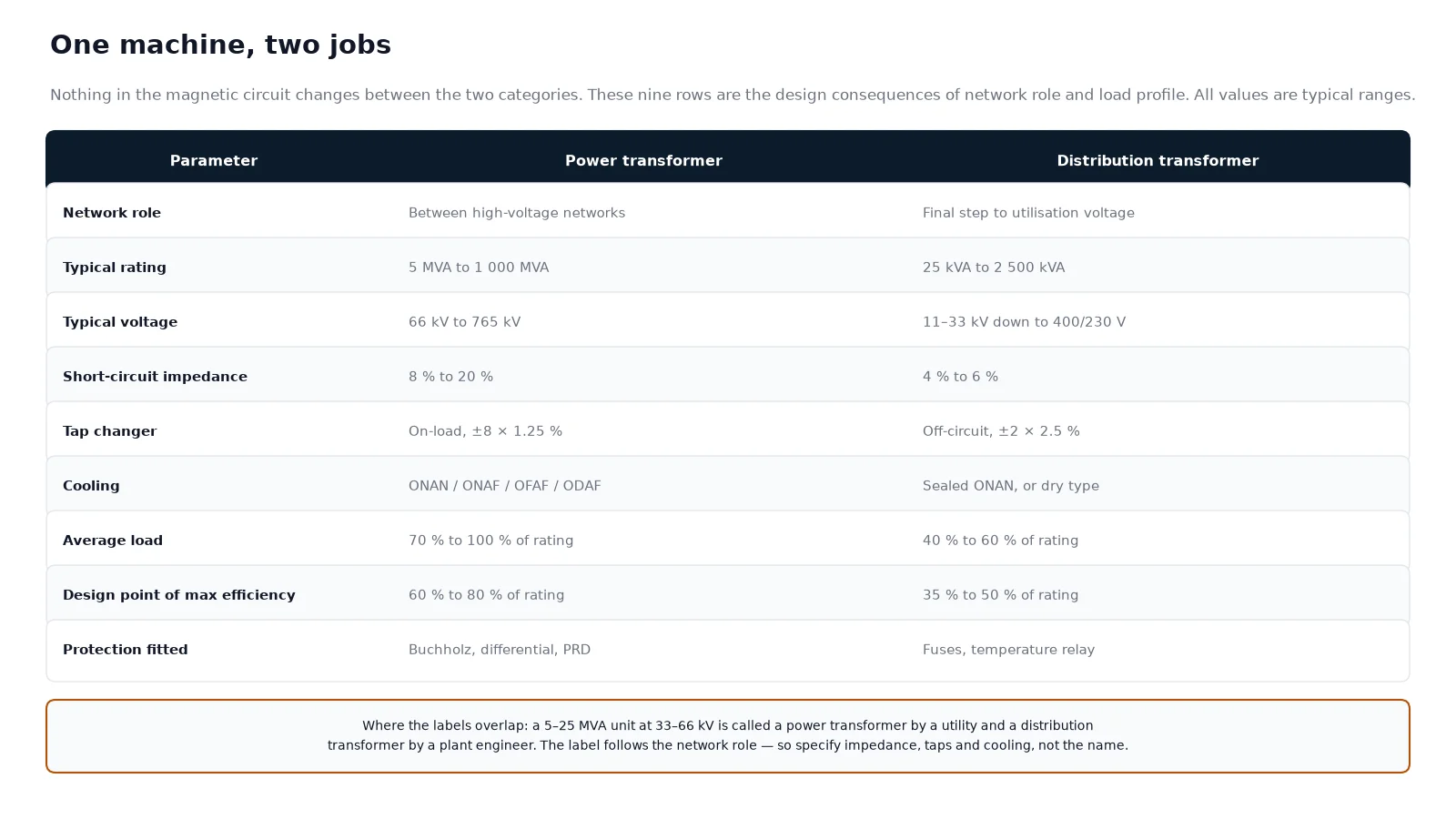
A power transformer moves bulk power between high-voltage networks. It sits at a generating station, at a transmission substation, or at the entry point of a large industrial plant, and it is rated from a few MVA to over 1 000 MVA. A distribution transformer takes medium voltage down to the voltage that equipment actually uses, typically 11, 22 or 33 kV to 400/230 V, and is rated from about 25 kVA to 2 500 kVA. Distribution units are numerous, cheap per unit and spread across the network; power transformers are few, expensive and concentrated where the voltage levels change.
Two rules of thumb are worth remembering, because they explain most of the design divergence:
- Voltage class sets the insulation. Everything above roughly 66 kV needs a bushing and insulation system that behaves very differently from a 400 V winding, and BIL rather than temperature becomes the dominant constraint.
- Load profile sets the loss balance. A unit that runs near its rating all day is designed to keep copper loss low. A unit that spends its life at a third of its rating is designed to keep core loss low.
Where the boundary actually sits
There is no single standard that draws a line at a fixed kVA. The labels come from three different places, and they do not agree, which is exactly why the confusion persists.
Network function. This is the definition most utilities actually use. If the unit transfers power between two transmission or sub-transmission voltage levels, it is a power transformer. If it delivers power to a load area at utilisation voltage, it is a distribution transformer. A 20 MVA 132/33 kV unit is a power transformer by this rule; a 1 000 kVA 33/0.4 kV unit is a distribution transformer.
Product standards. IEEE C57.12.20 covers overhead-type distribution transformers from 5 to 500 kVA. That is the scope of one product standard for one mounting arrangement, not a definition of the category — yet it is quoted constantly as if 500 kVA were a technical ceiling. It is not.
Efficiency regulation. Market rules add their own thresholds. The US DOE efficiency standards treat liquid-immersed distribution transformers as units up to 2 500 kVA and 34.5 kV, and the EU Ecodesign regulation uses a similar band. These thresholds exist so that regulators know which units to test, not because the physics changes at 2 500 kVA.
One more term causes trouble: “substation transformer”. It describes a location, not a design. A substation can hold a 250 MVA transmission unit or a 1 500 kVA distribution unit, and the two have nothing in common except the fence around them.
Why the two are designed around different loss balances
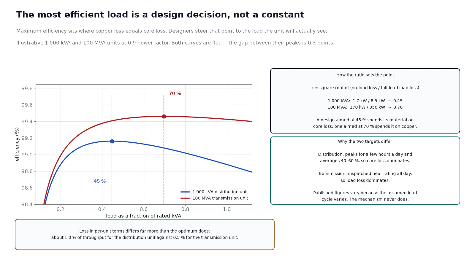
Every transformer has two loss components. No-load loss — core loss, from hysteresis and eddy currents in the steel — is present the moment the unit is energised and does not change with load. Load loss — copper loss, proportional to current squared — rises with the square of the load. The two are equal at the point of maximum efficiency, and that load fraction is fixed by the design ratio of the two losses:
x = square root of (no-load loss / full-load copper loss)
So a designer who wants maximum efficiency at 40 % of rating builds a unit where copper loss at full load is about six times the no-load loss. A designer who wants maximum efficiency at 80 % builds a unit where the two are almost equal at full load. Same transformer, same physics, different commercial target.
For distribution units that target sits low, usually between 35 % and 50 % of rating, because that is where the unit actually spends its hours. For transmission units the target sits higher, usually 60 % to 80 %, because the unit is dispatched and runs near its rating for most of its life. Published figures for this split vary between sources — some quote 50 % to 70 % for distribution designs — because the answer depends on the assumed load cycle, not on a standard. The mechanism is what matters: the optimum is a design decision, not a physical constant.
Loss magnitude differs far more than the optimum does. A modern 1 000 kVA distribution transformer with around 1.7 kW no-load loss and 10.5 kW load loss dissipates roughly 1.2 % of its throughput at full load. A 100 MVA transmission unit with 55 kW no-load and 350 kW load loss dissipates about 0.4 %. In per-unit terms the power transformer is three times tighter, which is why efficiency clauses on large units are negotiated in tenths of a percent and on distribution units in whole percent. The efficiency class and loss evaluation guide covers how those guarantees are measured and compared.
Impedance: the number that decides fault current and voltage drop
Short-circuit impedance, expressed as a percentage, is the parameter buyers should compare first and usually compare last. It sets two things at once: how much fault current the unit lets through, and how much voltage it loses when loaded.
| Parameter |
Distribution transformer |
Power transformer |
| Typical impedance |
4 % to 6 % |
8 % to 20 %, rising with rating and voltage |
| Reason for the value |
Low enough to keep voltage regulation tight at the end of the feeder |
High enough to limit fault current so downstream switchgear stays affordable |
| Effect of a higher value |
Better fault limitation, worse voltage drop, more reactive loss |
Cheaper switchgear and cables, larger voltage excursion on load steps |
| Effect of a lower value |
Better regulation, higher fault level at the LV board |
Higher fault level, heavier breaker ratings across the substation |
IEC 60076-5 allows a tolerance on the declared value of plus or minus 7.5 % when the impedance is 10 % or above, and plus or minus 10 % below that. Two units that both claim 6 % can therefore differ by 1.2 percentage points and still be compliant, which is enough to change the LV fault level by a few kA. If two transformers are going to run in parallel, keep their impedances within about 10 % of each other and their ratios and vector groups identical, or the load will not share as designed. The impedance and voltage drop guide works through the arithmetic.
Taps: off-circuit on the pole, on-load at the substation
A distribution transformer normally carries an off-circuit tap changer, five positions at plus or minus 2 × 2.5 %, adjusted with a link plate or a handwheel while the unit is de-energised. It exists to trim the ratio once, at commissioning, to match the actual feeder voltage. Nobody operates it afterwards, because the voltage is regulated upstream at the substation, and because an on-load tap changer would cost more than the transformer.
A power transformer usually carries an on-load tap changer, commonly plus or minus 8 × 1.25 % or plus or minus 10 %, with the motor drive controlled by an automatic voltage relay. It exists because a transmission transformer has to hold its secondary voltage while the load swings by hundreds of MVA and the upstream network moves. That is a different job, and it brings a different maintenance burden: diverter contacts, oil filter units, motor drives and a separate oil compartment that has to be sampled. The OLTC versus DETC comparison sets out the operating and maintenance consequences.
Cooling, enclosure and the maintenance that follows
Most distribution transformers are sealed ONAN units, or dry-type units in indoor installations where oil is not acceptable. Sealed means no conservator, no silica gel breather and no oil-level gauge to watch — a deliberate trade of serviceability for a maintenance interval measured in years. Pole-mounted and pad-mounted formats exist because the unit has to live where the load is, which is usually a street.
Power transformers are built for access instead. They carry a conservator, a Buchholz relay, a pressure relief device, winding and oil temperature indicators, and cooling that stages from ONAN to ONAF and then to forced oil with pumps and fans. Those stages only pay for themselves on a large unit, and they only work if someone maintains the pumps. The cooling class guide explains how the four-letter code maps to real capacity.
Loading practice: why a distribution unit runs at half load
Distribution transformers are sized for a load that peaks for a few hours and averages much lower; utilisation factors of 40 % to 60 % are normal, and oversizing to cover a five-year load forecast is routine. The consequence is that the unit spends most of its life dissipating almost nothing but core loss, which is exactly what its design targets.
Power transformers are loaded close to nameplate for most of the year, and their loading is planned rather than forecast. IEC 60076-7 gives the thermal basis for short-term overload, and the limits are set by hot-spot temperature and the loss of insulation life, not by a fixed percentage. A transmission unit can carry 120 % for a few hours if the ambient is low and the top-oil temperature allows it; the same overload on a sealed distribution unit with a 65 K rise is a different calculation, and usually a shorter one.
The overlap cases that cause specification mistakes
Three project types sit squarely in the grey zone, and each has a standard way of going wrong.
- Industrial 33/11 kV or 11/6.6 kV distribution. Rated 5 to 20 MVA, high voltage, but functionally a distribution step-down to plant voltage. Buyers often inherit a utility distribution specification and then discover it demands an OLTC and 12 % impedance that the plant does not need — or the reverse, a distribution-grade unit with 4.5 % impedance that puts 40 kA on the plant switchboard.
- Renewable collector substations. A 60 MVA 33/132 kV unit is a power transformer by role, but its load profile is nothing like a transmission unit’s: it follows an inverter or a wind farm, with daily cycling and harmonics. Impedance and harmonic loss design both need to be specified, and neither is covered by a generic power transformer datasheet.
- Large commercial and data centre intake. A 2 500 kVA 11/0.4 kV unit is a distribution transformer by rating, but it runs at high load factor with non-linear current, which pushes it toward K-factor or derated design and often toward dry type for fire reasons.
A selection checklist for projects in the grey zone
Ignore the label and answer these five questions. The answers determine the specification, and the label usually follows.
- What is the expected average load, not the peak? That number sets the loss balance and therefore the most economical design point.
- What fault level can the downstream equipment accept? Work backwards from the switchgear rating to an impedance range, then check the voltage drop at that impedance.
- Will the source voltage move more than the load can tolerate? If yes, you need an OLTC; if the upstream substation already regulates, an off-circuit tap is enough.
- Is oil acceptable on site? Fire, bunding, and insurance rules can force dry type regardless of rating, and dry type changes the impedance, the footprint and the noise.
- How will the unit be maintained? A sealed distribution unit suits a site with no electrical staff. A unit with pumps, an OLTC and a conservator does not.
Get those five right and the kVA follows from the load calculation, not from a category name. The power transformer definition page covers the construction side, and the mounting question — pole versus pad mounted — becomes the next decision for anything in the distribution band.
Conclusion
Power transformer and distribution transformer describe two network roles, not two technologies. The power transformer moves bulk energy between high-voltage networks, runs near its rating, and is built with high impedance and an on-load tap changer to keep the transmission system stable. The distribution transformer delivers that energy at usable voltage, runs at part load, and is built with low impedance and a fixed tap to keep the customer’s voltage steady at the lowest cost.
When a project falls between the two, specify from the load profile and the fault level rather than from the label. If you are weighing the two for a specific rating, send the primary and secondary voltage, the expected average and peak load, and the downstream fault rating — the power transformer range covers both oil-immersed and cast resin units across the 11 to 40.5 kV classes where the overlap usually happens.
FAQ
Is a distribution transformer a type of power transformer?
Yes, in the sense that every distribution transformer is a power transformer by function and is built and tested to the same core standards, IEC 60076-1 for liquid-immersed units and IEC 60076-11 for dry type. “Power transformer” in the narrow sense means a unit in the transmission network. In the wide sense, which is the one used in standards, it covers everything that transfers power between circuits.
What is the kVA boundary between the two?
There is none that is technically fixed. Utilities usually draw the line by network function, regulators draw it at 2 500 kVA for efficiency testing, and IEEE C57.12.20 ends at 500 kVA for overhead distribution products. In practice, units below about 2 500 kVA at 33 kV and under are treated as distribution, and units above 10 MVA at 66 kV and above are treated as power.
Why is the impedance of a power transformer higher?
Because its job is to interconnect two networks, and those networks are protected by expensive switchgear whose fault rating is fixed. Raising the transformer impedance reduces the fault current the downstream equipment has to interrupt, and the price paid is a larger voltage drop and more reactive consumption — both acceptable at transmission level, where voltage is actively regulated.
Can a distribution transformer have an on-load tap changer?
It can, and in weak or long rural feeders it sometimes does. The economics usually do not support it: an OLTC adds cost, a separate oil compartment and a maintenance item to a unit that is meant to run unattended for years. Where voltage control is needed, utilities normally install a separate voltage regulator or reinforce the feeder instead.
Which type is more efficient?
Large power transformers are more efficient, typically 99.5 % or better at full load, against 98.5 % to 99 % for distribution units. The comparison is not really fair: efficiency rises with size in every electrical machine, and a distribution unit of 500 kVA cannot reach transmission-grade efficiency at any price. What is fair is comparing units of the same rating against the same efficiency class and loss evaluation.
Does a substation transformer count as a power transformer?
It depends on what it does, not where it stands. A unit that connects two transmission voltage levels inside a substation is a power transformer. A unit that steps 33 kV down to 400 V inside the same substation is a distribution transformer. The term describes the location and says nothing about the design.