CT Ratio Selection: Table, Calculation and Metering Rules
Published: Author: Lisa
A current transformer ratio is written as two numbers separated by a slash, and almost every metering and protection problem traced back to a CT starts with those two numbers being wrong. 200/5 means 200 A primary produces 5 A secondary, so the ratio is 40:1. Choose the primary too low and the CT saturates on overload; choose it too high and the secondary current at light load falls into the region where accuracy collapses and the meter stops resolving anything useful.
This guide gives you the standard ratio table, the calculation method, the rules that decide the primary rating and the secondary rating, and the mistakes that show up most often in factory acceptance tests. If you are specifying ratios for a switchgear package, the current transformer range shows the physical formats these ratios come in, from 10 kV cast resin indoor units to 35 kV outdoor columns.
The Three Numbers Behind Every CT Ratio
A CT nameplate carries three related values that people confuse constantly. The rated primary current is the current the primary winding is designed to carry continuously. The rated secondary current is what appears at the terminals — 5 A in most of the world, 1 A in high-voltage substations and long secondary runs. The ratio is simply the first divided by the second.
What the ratio is not is a turns ratio in the literal sense. A 200/5 CT does not necessarily have exactly 40 turns on the primary, because the actual transformation depends on the core, the burden and the exciting current. The nameplate ratio is the ratio at rated burden and rated accuracy, and the real ratio deviates from it by a small amount that the accuracy class defines. That deviation is why a 0.5 class CT is allowed a ratio error of ±0.5% at rated current and why a 5P10 protection CT is allowed 5% composite error at its accuracy limit.
Standard CT Ratio Table
Ratios are not arbitrary. IEC 61869-2 builds them from the R10 preferred number series applied to rated primary currents, which is why the same numbers appear across manufacturers. The table below covers the range that handles most distribution and industrial work at a 5 A secondary.
Primary current
Ratio (5 A secondary)
Ratio (1 A secondary)
Typical application
50 A
50/5
50/1
Small LV feeder metering, capacitor banks
100 A
100/5
100/1
Distribution board incomers, small motors
200 A
200/5
200/1
400 V feeder protection and metering
400 A
400/5
400/1
Transformer LV side, 630 kVA class
600 A
600/5
600/1
1,000–1,250 kVA transformer LV side
800 A
800/5
800/1
1,600 kVA transformer LV side
1,000 A
1,000/5
1,000/1
2,000 kVA transformer LV side, busbar metering
1,500 A
1,500/5
1,500/1
Main LV switchboard incomers
2,000 A
2,000/5
2,000/1
High-current LV distribution
3,000 A
3,000/5
3,000/1
Generator output, large rectifier feeds
Between those numbers sit the intermediate values used in specific markets — 300/5, 500/5, 750/5, 1,250/5. They exist because the primary current of a real installation rarely lands on a preferred number. The engineering rule is not “pick the closest standard ratio” but “pick the standard ratio that keeps the measured current inside the accuracy window at both maximum and minimum load.”
How to Calculate the CT Ratio
The calculation has four steps, and the order matters because each step constrains the next.
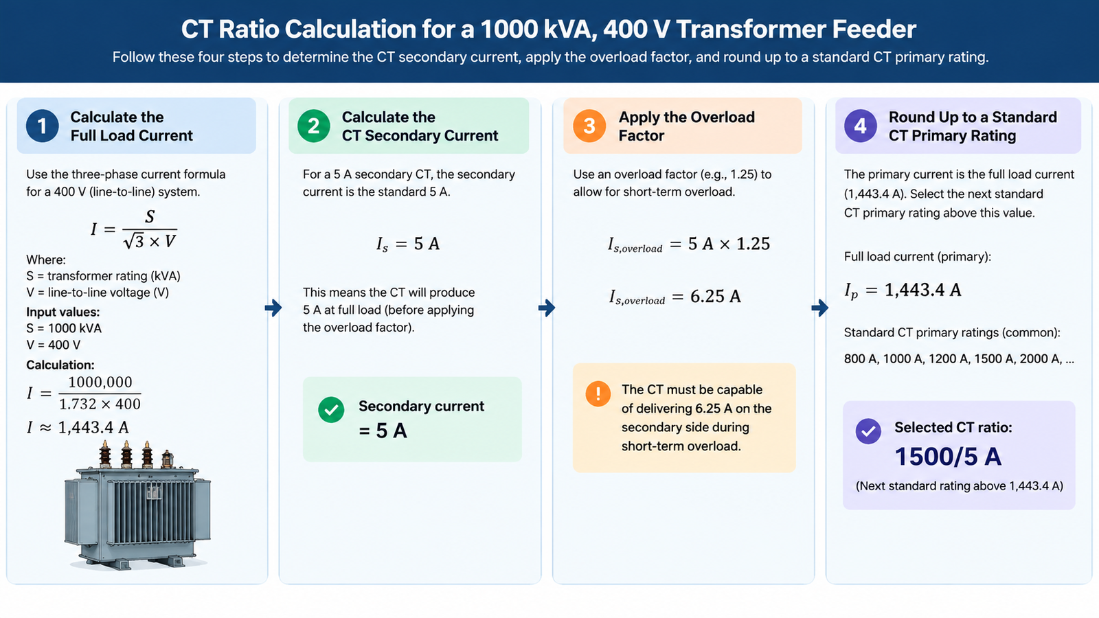
Find the maximum continuous primary current. For a transformer feeder this is the transformer’s rated secondary current, not the switchgear rating. A 1,000 kVA, 400 V transformer carries 1,443 A, so the CT primary must be at least that.
Add the overload allowance. Apply 1.1 to 1.2 times the maximum continuous current so the CT is not operating near its thermal limit during normal peaks. For the example above, 1,443 × 1.15 ≈ 1,660 A.
Round up to the next standard primary rating. 1,660 A rounds to 2,000/5. Rounding down to 1,500/5 would place the CT below the calculated maximum and force it into continuous overload.
Confirm the secondary current at minimum load is still measurable. At 10% of rated primary, a 2,000/5 CT delivers 0.5 A — well within the working range of a 5 A meter, but only if the meter’s starting current is low enough. This is where extended-range accuracy classes matter.
The formula in one line: CT primary ≥ 1.1 × maximum continuous load current, then round up to the next preferred value. The 1.1 factor is a working number, not a code requirement — where the load profile is well documented and the CT has thermal margin, 1.0 can be defensible, and where the load is expected to grow, 1.25 is more realistic.
Choosing the Primary Rating: What Actually Constrains It
Three separate limits set the primary rating, and the largest one wins.
Thermal limit. A CT must carry the maximum continuous current without exceeding its insulation temperature class. Continuous thermal current ratings are usually 100% to 120% of rated primary, so a 400/5 CT rated for 120% handles 480 A indefinitely. Beyond that, the winding ages faster and the ratio drifts.
Accuracy limit for metering. Instrument security factor (FS) defines the multiple of rated primary current at which the composite error reaches 10%. An FS 5 metering CT stays within its accuracy class up to five times rated current. If the actual fault current is 20 kA on a 400/5 CT — 50 times rated — the CT saturates deliberately and protects the meter. That is the intended behaviour, not a fault.
Accuracy limit factor for protection. A protection CT works the other way. 5P10 means the composite error stays within 5% up to ten times rated primary current. A 400/5 5P10 CT therefore remains usable to 4,000 A, which must exceed the maximum through-fault current the relay has to see clearly. Where it does not, either the ratio moves up or the ALF moves up — and ALF is usually the cheaper change.
1 A or 5 A Secondary: The Decision That Is Really About Cable
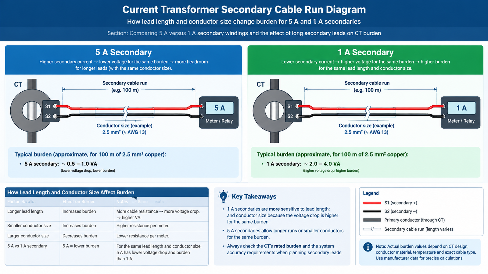
The secondary rating is not a market preference, it is a lead-length calculation. Secondary burden is proportional to the square of the current, so a 5 A secondary produces 25 times the VA of a 1 A secondary for the same lead resistance. The consequence is simple: 5 A secondaries belong in switchgear where the CT-to-meter run is a few metres, and 1 A secondaries belong where that run is tens or hundreds of metres.
Factor
5 A secondary
1 A secondary
Burden on long leads
High — 25× that of 1 A for the same resistance
Low
Practical lead run
Under 10–20 m
Up to several hundred metres
Burden ratings available
2.5 to 30 VA typical
5 to 30 VA typical
Meter and relay compatibility
Nearly universal
Requires 1 A input devices
Winding cost
Lower
Higher — more secondary turns
Vibration and loose-terminal sensitivity
Higher current, more tolerant of contact resistance
More sensitive to termination quality
Mixing the two in one installation is possible but expensive — separate 1 A and 5 A cores, or interposing transformers. Decide once, at the single-line diagram stage.
Matching Ratio to Accuracy Class and Burden
A ratio on its own does not define a CT. The same 400/5 unit can be a 0.5 class metering CT at 15 VA or a 5P10 protection CT at 20 VA, and those are different products. Burden is the total impedance of the secondary circuit — cable resistance, relay or meter impedance, and contact resistance — expressed in volt-amperes at rated secondary current.
The rule is that the CT’s rated burden must be at least 25% higher than the calculated actual burden, to cover temperature drift and connection changes. A metering circuit with a 3 VA meter and 4 m of 2.5 mm² leads calculates to roughly 5 VA; a 7.5 VA or 10 VA CT covers it. Undersizing burden is one of the more common specification errors because the leads are the part nobody measures. The relationship between ratio, class and burden is set out in more detail in the guide to CT ratios, accuracy classes and VA ratings.
Where Ratio Selection Goes Wrong
Mistake
What happens
Correction
Sizing to transformer kVA instead of secondary current
Ratio two steps too high; meter reads 30–50% of expected at light load
Use rated secondary current × 1.1–1.2
Ignoring load growth
CT runs above 100% thermal continuously after expansion
Apply 1.25 where growth is planned
Choosing 5 A secondary for a 150 m run
Lead burden exceeds rated VA; ratio error grows with current
Switch to 1 A secondary or 6 mm² leads
Using a metering CT class for protection
CT saturates during fault; relay under-reaches
Specify 5P or 10P with adequate ALF
Assuming ratio accuracy is constant across the range
Large error below 20% of rated current
Use 0.2S or 0.5S for wide-load metering
Forgetting the burden of the test terminal block
Actual burden 15–20% above calculation
Add 1–2 VA for terminals and wiring
Reading a Ratio From the Nameplate
A typical 10 kV indoor cast resin nameplate reads 400/5 A, 15 VA, class 0.5, FS 5, 50 Hz, 12 kV, BIL 75 kV. Decoded: the CT delivers 5 A at 400 A primary; it holds ±0.5% ratio error up to 15 VA of burden; it stays within class to five times rated current; and the insulation is rated for 12 kV system voltage with a 75 kV basic impulse level. The current transformer construction and insulation details behind those numbers are covered separately.
When the same primary current requires both metering and protection, the usual configuration is two cores in one housing — for example 400/5 class 0.5 FS 5 for the meter and 400/5 5P10 20 VA for the relay. Real units of this configuration are the LZZBJ9-10 indoor cast resin CT and the higher-output LZZBJ12-10; the differences between them are worked through in the LZZBJ9-10 versus LZZBJ12-10 comparison. For outdoor 35 kV work the LZZBW-35 column CT series covers the same ratio logic at a higher insulation level.
Conclusion
Pick the primary current from the maximum continuous load plus an overload allowance, round up to a preferred standard ratio, choose the secondary from the length of the secondary run, then confirm that the accuracy class, ALF and burden still do their jobs at both ends of the load range. Get those four decisions in that order and the ratio stops being a guess. If you are working through a specific switchgear or substation package, sending the single-line diagram and the relay models is usually faster than specifying ratios in isolation.
Frequently Asked Questions
What does 200/5 mean on a CT?
It means 200 A flowing in the primary produces 5 A in the secondary, giving a 40:1 ratio. Multiply the secondary reading by 40 to get the primary current.
How do I calculate the CT ratio for a transformer?
Divide the transformer’s rated capacity by its secondary voltage and √3 for a three-phase unit, then multiply by 1.1 to 1.2 for overload, and round up to the next standard primary rating. A 1,000 kVA 400 V transformer needs a 2,000/5 CT.
Can I use a 400/5 CT for 100 A load?
You can, but at 25% of rated primary the accuracy degrades. A class 0.5 CT may exceed its tolerance; a 0.5S class CT with extended range holds accuracy down to 1% of rated current and is the correct choice for loads that swing widely.
What is the difference between CT ratio and turns ratio?
The nameplate ratio is the current transformation at rated burden and class. The physical turns ratio is slightly different because exciting current and losses prevent a perfect transformation; the difference appears as ratio error.
Why are CT ratios usually 5 A instead of 1 A?
5 A secondaries suit short secondary runs inside switchgear and match most meters and relays. 1 A secondaries reduce lead burden by a factor of 25 and are used where CTs are far from the panel.
What does FS 5 mean on a metering CT?
Instrument security factor 5 means the composite error reaches 10% at five times rated primary current. Beyond that the CT saturates on purpose, limiting the energy delivered to the meter during a fault.
Step-up and step-down oil-immersed transformers differ in taps, impedance, cooling and loss weighting. Here is how to specify each duty for generation and distribution.
Compare solid, low resistance, high resistance, resonant and ungrounded MV neutrals, and size the grounding transformer and resistor that go with each method.
Why partial discharge decides cast resin transformer life: the 10 pC limit, how the IEC 60270 test runs, what the pC reading means, and the casting defects behind it.