CT Accuracy Class Explained: 0.2, 0.5, 5P10, 10P10
Published: Author: Lisa
A current transformer accuracy class is the number that tells you how wrong the CT is allowed to be, and it is the single specification most often copied from a previous project without anyone checking whether the application still justifies it. The notation looks cryptic — 0.5, 0.2S, 5P10, 10P10 — but it follows one consistent logic: metering classes describe an error limit as a percentage, protection classes describe an error limit as a percentage plus a multiple of rated current.
This article decodes each class, explains what the letters and numbers do, shows where the boundaries sit between metering and protection, and covers the burden relationship that quietly overrides the class on real installations. For the physical formats that carry these classes, the current transformer product range is the starting point.
How the Accuracy Class Notation Is Built
Every CT accuracy class is a compressed instruction. Read it left to right.
0.5 — a metering class. The CT’s ratio error must stay within ±0.5% at rated primary current, and its phase displacement within a defined angle.
0.2S — a metering class with the S suffix. Same ±0.2% ratio error at rated current, but the tolerance is then held down to 1% and up to 120% of rated current instead of the standard 5% to 120% window.
5P10 — a protection class. The 5 is the maximum composite error in percent, the P means protection, and the 10 is the accuracy limit factor (ALF): the CT holds that 5% error up to ten times rated primary current.
10P10 — the same structure with a looser error limit: 10% composite error up to ten times rated current.
So 5P10 is not “5% accuracy, class 10.” It is “5% composite error, guaranteed up to 10× rated current.” That single misreading causes more wrong specifications than any other in instrument transformer work.
Metering Classes: 0.1 Through 3.0
Metering classes run from 0.1 (laboratory and calibration reference) to 3.0 (coarse indication only). IEC 61869-2 sets both ratio error and phase displacement limits, and the phase displacement matters as much as the ratio error because energy meters compute power from the product of voltage and current, and an angular error translates directly into a power measurement error.
The practical consequence of moving from 0.5 to 0.2 is a factor of 2.5 in allowable error, which on a large billing point can be worth more than the CT costs. On a 2,000 kVA industrial supply at 11 kV, the difference between a 0.5 and a 0.2 class metering CT can move annual energy settlement by a measurable amount. Industrial sub-metering rarely justifies 0.2; utility revenue metering almost always does.
What the “S” Suffix Actually Changes
A standard class 0.5 CT is only required to meet its tolerance from 5% of rated current upward. Below that, the error is unconstrained. A 400/5 class 0.5 CT can therefore be quite wrong at 10 A primary, which is 2.5% of rating.
The S classes extend the lower bound to 1% of rated current, and separately tighten the error limit at the 5% and 20% points. This matters wherever the load spends real time at low current: a plant running nights and weekends at 8% of peak, a feeder whose load varies by an order of magnitude across a shift, or a renewable connection where output swings with weather.
Two related numbers complete the metering picture. The instrument security factor (FS) defines the multiple of rated current at which the composite error reaches 10%; FS 5 and FS 10 are the common values, and a lower FS gives better meter protection during faults. The rated burden defines the volt-amperes the CT can drive while holding its class — the more burden, the more the class suffers. The interaction between ratio, class and burden is worked through in the guide to CT ratios, 0.5 class accuracy and VA ratings.
Protection Classes: 5P and 10P
Protection CTs are specified for a different job. The relay does not need a precise current at normal load; it needs a faithful, undistorted image of the current during a fault, which may be twenty or forty times rated current. So the specification shifts from “how accurate at rated current” to “how long does accuracy hold as current rises.”
The accuracy limit factor (ALF) is that answer. A 5P20 CT holds 5% composite error up to 20× rated primary current. On a 400/5 CT, that is 8,000 A — comfortably above the maximum fault current the relay must measure without distortion.
The 5P versus 10P choice is not about quality. A 10P20 CT is entirely adequate for a feeder over-current relay that only needs to know a fault exists. A 5P class becomes necessary when the relay performs a measurement or a comparison — differential, distance, or directional elements, where a distorted current produces a wrong decision rather than a slow one.
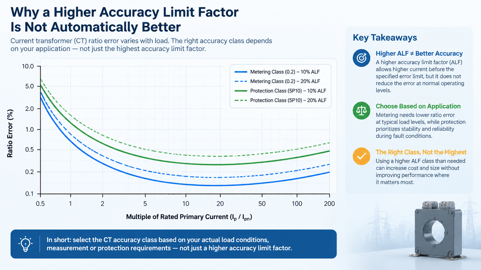
Why Higher ALF Is Not Automatically Better
A higher ALF means a larger core, more iron, more weight and more cost. It also means the CT will faithfully reproduce very high fault currents, which the downstream equipment may not want. Two constraints bound the choice.
The lower bound is the maximum through-fault current at the CT’s location, with some margin. If the switchgear is rated 25 kA and the CT ratio is 400/5, the CT sees 62.5× rated current during a fault; a 5P10 unit would saturate long before that. Whether that matters depends on whether the relay needs to measure the fault or merely detect it — over-current elements typically do not.
The upper bound is the connected burden. ALF is quoted at rated burden. If the actual burden is lower than rated, the effective ALF rises; if it is higher, the effective ALF falls, and the CT saturates earlier than the nameplate promises. This is the mechanism behind a surprising number of protection misoperations: the CT was correct, the burden was not.
Selecting the Class by Application
Application
Recommended metering class
Recommended protection class
Utility revenue metering at the point of supply
0.2 or 0.2S
5P20
Commercial building tenant billing
0.5S
5P10
Industrial plant sub-metering
0.5 or 0.5S
5P10
Panel instrumentation only
1.0
Not applicable
Transformer differential protection
0.5
5P20 or PX, matched pair
Motor protection
1.0
10P20
Capacitor bank switching
Not required
5P10
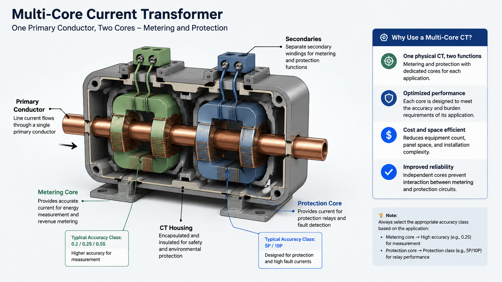
Where one physical CT must serve both functions, the standard solution is a multi-core unit — one 0.5 class metering core and one 5P protection core in the same housing, sharing a primary conductor but with separate magnetic circuits. The overall selection framework for both current and voltage transformers is set out in the guide to instrument transformer accuracy classes and specifications.
How Accuracy Class Is Verified
Class is a tested claim, not a design intent. Type tests establish the design; routine tests confirm each unit. The tests that matter for class verification are:
Ratio error and phase displacement test at 5%, 20%, 100% and 120% of rated current, at rated burden and at 25% of rated burden — the two-burden test is what catches units that only meet class at one operating point.
Burden measurement, to confirm the rated VA figure is real rather than nominal.
Excitation or saturation curve, from which the composite error at ALF is calculated for protection cores.
Polarity check, which is a pass/fail gate rather than a class issue but causes more commissioning problems than any accuracy deviation.
Read as 5% composite error up to 10× rated current
Specifying 0.2 for industrial sub-metering
Cost with no billing benefit
0.5S is sufficient for allocation and load studies
Using a metering class for protection
CT saturates during fault; relay under-reaches
Specify 5P or 10P with calculated ALF
Ignoring actual burden when checking ALF
Effective ALF lower than nameplate
Recalculate ALF at the measured burden
Standard 0.5 class on a highly variable load
Uncontrolled error below 5% of rated current
Use 0.5S or 0.2S for extended range
Mismatched cores in a differential scheme
Spurious differential current at through-fault
Match class, ratio and burden across both sides
Conclusion
Read the class as two separate promises: what the error is allowed to be, and over what current range that promise holds. Metering classes answer the first question directly; protection classes answer it plus a multiplier. Then check the burden, because class without adequate burden is a number on a nameplate rather than a guarantee in service. The companion guide on CT ratio selection and the standard ratio table covers the other half of the specification — which primary and secondary values to pair with the class you choose.
Frequently Asked Questions
What does class 0.5 mean on a current transformer?
It means the ratio error must stay within ±0.5% and the phase displacement within ±30 minutes at rated primary current and rated burden, for currents from 5% to 120% of rating.
What is the difference between 0.2 and 0.2S?
Both allow ±0.2% ratio error at rated current. The S version extends the tolerance range down to 1% of rated current and tightens the limits at low current points, which suits loads that vary widely.
What does 5P10 mean?
5% maximum composite error, protection class, guaranteed up to ten times rated primary current. The 10 is the accuracy limit factor, not an accuracy figure.
Is 10P10 better or worse than 5P10?
It is looser, not better: 10% composite error instead of 5%, with the same 10× accuracy limit. It is adequate for detection-only protection such as basic over-current and earth-fault elements.
Can a metering CT be used for protection?
Generally no. Metering CTs are built with a low instrument security factor so they saturate deliberately during faults to protect the meter, which destroys the current waveform the relay needs.
How does burden affect accuracy class?
Every class is quoted at rated burden. Exceeding it increases error and lowers the effective accuracy limit factor; staying well below it improves both. Specify rated burden at least 25% above the calculated actual burden.
Step-up and step-down oil-immersed transformers differ in taps, impedance, cooling and loss weighting. Here is how to specify each duty for generation and distribution.
Compare solid, low resistance, high resistance, resonant and ungrounded MV neutrals, and size the grounding transformer and resistor that go with each method.
Why partial discharge decides cast resin transformer life: the 10 pC limit, how the IEC 60270 test runs, what the pC reading means, and the casting defects behind it.