
Description
GKJ5 Three-Phase at a Glance
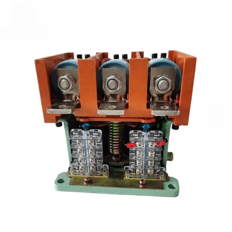
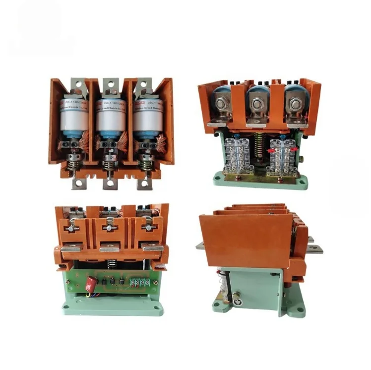
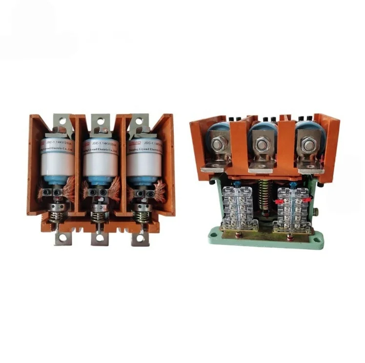
The GKJ5 three-phase vacuum contactor is a 1,140 V low-voltage switching unit built into a vertical three-pole frame, with the interrupter column upright in a standard cubicle. It uses a DC magnetic system fed through a rectifier bridge from an AC control supply, and carries three normally open plus three normally closed auxiliary contacts.
It is the three-phase counterpart to the single-phase frame in the same family, sharing the environmental envelope and the mechanical life, but built for motor and transformer duty on 1,140 V mining and plant networks.
The DC Magnetic System and Rectifier Bridge
This is the part of the design that separates the GKJ5 three-phase vacuum contactor from a plain AC-operated unit, and it is worth understanding before specifying a control supply.
The control power supply is alternating current. It is fed through a rectifier bridge to produce direct current for the operating coil. Once the armature has pulled in, a current-limiting resistor is switched into the coil circuit.
Three things follow from that arrangement:
- No AC hum. A DC-energised coil produces steady flux, so the laminated core does not vibrate at twice line frequency. The contactor runs silently, which matters in a panel mounted next to an operator position.
- Lower holding current. The resistor reduces coil current after pull-in, because holding the armature closed needs far less force than pulling it in. That cuts continuous coil losses and the heat they put into the panel.
- Defined control-supply interface. The panel supplies AC, the contactor rectifies it internally. You do not need a separate DC supply, but you do need to confirm the control voltage the bridge is built for.
The consequence for the buyer is that the control voltage is a specification item, not an accessory. A unit built for 220 V AC control will not work on a 127 V supply, and the bridge is not field-configurable.
Ceramic Interrupter Housing
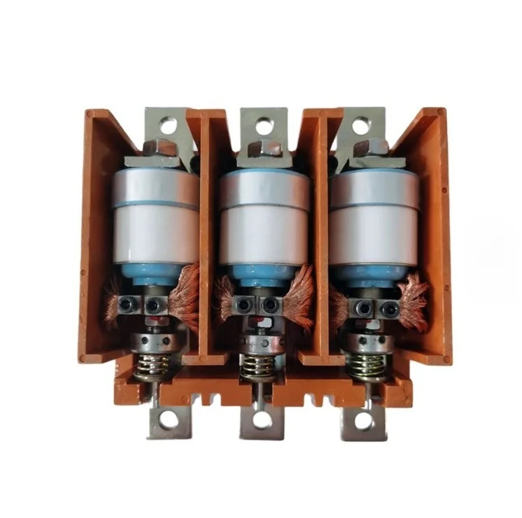
The vacuum interrupter shell is ceramic rather than glass or a moulded composite. Ceramic holds its dielectric strength at higher temperature and is more resistant to mechanical shock, which is why it is the standard choice for mining duty where the panel may see vibration and rapid thermal cycling.
It also means the interrupter is not a user-serviceable item. When the contact gap or the overtravel reaches its limit, the interrupter is replaced as a unit rather than having its contacts dressed.
Auxiliary Contacts and Control Wiring
The GKJ5 three-phase vacuum contactor provides three normally open and three normally closed auxiliary contacts as standard. For a typical motor starter that covers the holding circuit, the run indication, one interlock, and the complementary contacts for fault and ready signals.
Where the scheme needs more, an external auxiliary block is added at the panel. Confirm the count against the control drawing rather than assuming six will be enough, particularly on a starter that also reports to a supervisory system.
Outgoing Mode and Panel Layout
The published configuration of the GKJ5 three-phase vacuum contactor lists front-of-board outgoing, meaning the cable or busbar connection leaves toward the front of the panel rather than the rear. That suits a lineup where all maintenance access is from the front and the rear is against a wall.
It also fixes the cable bending radius. A front-exit arrangement needs the depth in front of the terminals for the cable to bend, which is a panel dimension that has to be checked before the cubicle is built rather than after.
Ratings
| Parameter | Published value |
|---|---|
| Main-circuit rated voltage | 1,140 V, 50 Hz |
| Number of main poles | Three |
| Voltage fluctuation tolerance | Normal operation up to 15% fluctuation |
| Contact opening distance | 2.0 (+0.2) mm |
| Contact overtravel | 1.0 (+0.2) mm |
| Rated working system | Long-term, and intermittent periodic at 40% on-time |
| Operating frequency, AC-4 | 240 operations/hour |
| Operating frequency, short time (20 s) | 2,000 operations/hour |
| Electrical life, AC-4 | Greater than 60,000 operations |
| Mechanical life | 3,000,000 operations |
| Control-circuit arrangement | DC magnetic system via rectifier bridge, current-limiting resistor after pull-in |
| Auxiliary contacts | 3 normally open + 3 normally closed |
Rated current is confirmed per configuration against the motor it will start. Send the motor rating, the starting method and the expected operations per hour, and the frame is quoted against those three rather than against a generic current figure.
Three-Phase Motor Sizing
Two checks decide whether the frame fits, and they use different numbers.
- Continuous current. The motor full-load current plus the margin your site standard requires. This sets the thermal duty, not the switching capability.
- Making capacity. A direct-online motor draws roughly six times full-load current at start, and the contactor has to close onto that. This is the check that usually forces a step up in frame size.
A worked example: a 110 kW 1,140 V motor draws about 65 A at full load, with a start current near 390 A. The continuous figure is well inside the frame, and the start figure is what the making capacity is checked against. If the same motor starts twice an hour, the operating frequency is not a constraint; if it inches or reverses, the AC-4 life becomes the limit rather than the mechanical life.
One more point specific to 1,140 V mining networks: the 15 percent voltage fluctuation tolerance means the contactor operates normally down to about 970 V and up to about 1,310 V. Beyond that band, the coil pull-in force or the holding force falls outside the design, which is a control-supply problem rather than a contactor problem.
Operating Environment
Altitude up to 2,000 m, ambient from -5 °C to +40 °C with a daily average not above 30 °C, daily average relative humidity below 95 percent and monthly average below 90 percent. The atmosphere must be free of steam, corrosive gas, salt fog, conductive dust and explosive media, and the mounting surface must not see regular vibration or severe shock.
Mounting inclination is limited to 15 degrees from vertical, and the installation category is normally category III. On a vertical frame the inclination limit is a real constraint: a sloped mounting loads the mechanism unevenly and shortens interrupter life.
When a Different Frame Fits Better
- Single-phase loads. The GKJ5 single-phase contactor covers that duty in the same family.
- Shallow drawer or restricted height. The CKJ5 horizontal contactor lays the interrupter sideways for low-profile panels.
- 380 V to 660 V duty at 250 A to 600 A. The CKJ5 horizontal frame covers those ratings with a simpler AC control arrangement.
The full range sits under vacuum contactor series.
Manufacturer Supply, OEM and Wholesale
The GKJ5 three-phase vacuum contactor is supplied direct. Panel builders order against a frozen control voltage and auxiliary contact specification under OEM or private-label marking; mining integrators hold a standing specification for repeat supply; project buyers receive test reports and outline drawings for approval.
Price, MOQ and Lead Time
- MOQ. Single units for standard configurations. Custom control voltages and private-label marking carry a higher minimum.
- Price drivers. Current rating, control voltage, auxiliary contact count and quantity.
- Lead time. Confirmed against the production schedule at order.
- Payment. Deposit with balance against the bill of lading copy; letter of credit for project quantities.
What to Send With Your Inquiry
- System voltage and frequency
- Motor rating, full-load current and starting method
- Duty category: AC-3, or AC-4 for inching and reversing
- Expected operations per hour
- Control-circuit voltage and supply type
- Auxiliary contact requirement
- Panel layout: front-of-board or rear outgoing
- Site altitude and ambient temperature range
- Quantity, destination port and required delivery date
Send those through the quote form on this page. The control voltage and the motor starting method are the two items that decide the configuration, so both belong in the first message.
FAQ
What is the DC magnetic system?
Do I need a separate DC supply?
Why a ceramic interrupter housing?
What is front-of-board outgoing?
How many auxiliary contacts?
What is the MOQ?
Request Quote
Tell us your specifications, quantity, or application scenario and we will reply with a tailored quote.