
Description
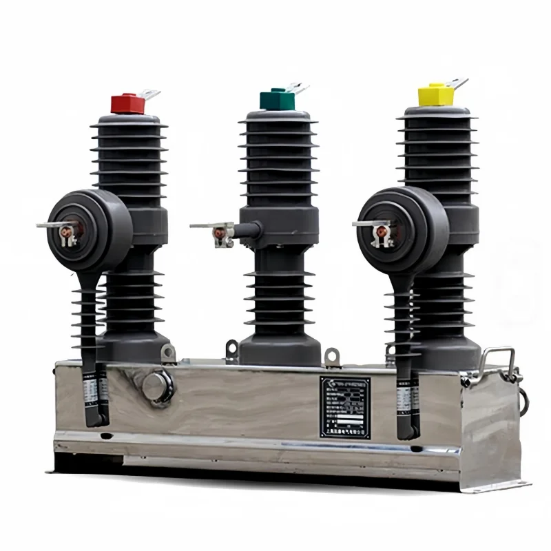
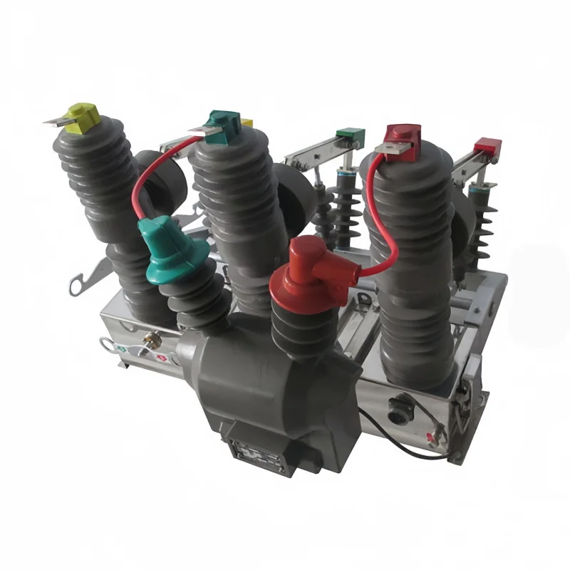
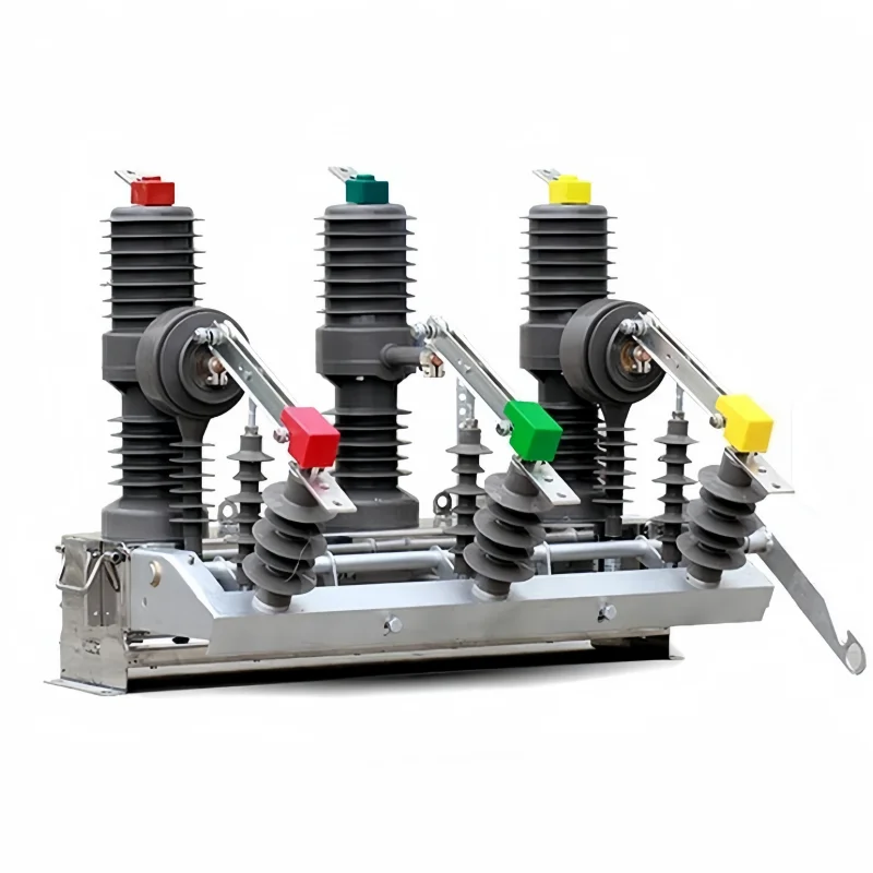
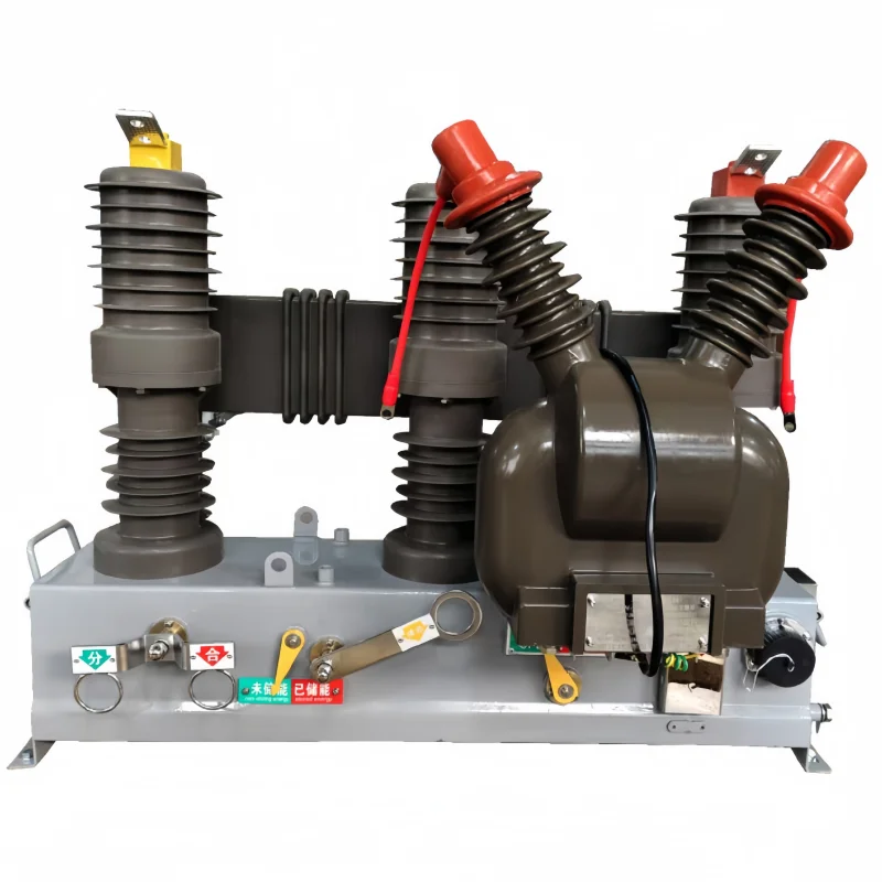
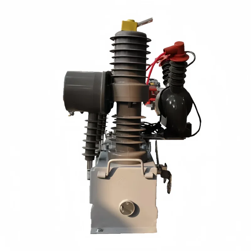
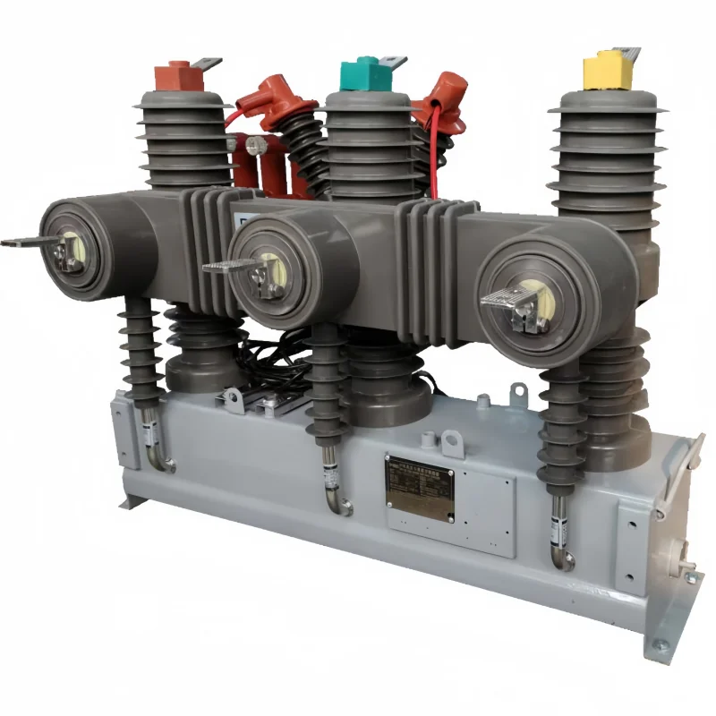
ZW32M is an intelligent vacuum circuit breaker built on the ZW32 outdoor frame: a pole mounted unit at 12 kV or 24 kV, fitted with a permanent magnet actuator and a protection controller so that it can be operated, watched and tripped by logic rather than by a handle. The interrupter and the pole assembly are the same as the standard frame. The difference is what surrounds them.
That difference is worth about one line in most quotations and about a season of commissioning in the field. A breaker described as “intelligent” or “with remote control” can mean anything from a motor-operated switch with a radio module to a unit that executes a full reclosing sequence and reports fault type. This page is about the second kind, and about the questions that separate the two before an order is placed.
What an Intelligent Vacuum Circuit Breaker Actually Is
On a distribution frame, an intelligent vacuum circuit breaker is usually sold on three layers, and a supplier can honestly claim the word while delivering only the first.
- Operable at a distance. The breaker accepts open and close commands from a control centre. This needs a communication path and a defined point list, nothing more. It is the cheapest layer and the one most often quoted as the whole package.
- Observable. Position, current, and sometimes temperature or capacitor state are reported back. This needs sensors inside the breaker or the cabinet, not just a modem, and it is where low-cost builds quietly fail to deliver.
- Decisive. The controller detects a fault, trips, waits a defined dead time, and recloses. The logic lives in the controller and the timing is an engineering decision. This is the layer that changes how a feeder is operated, and the one worth paying for.
A quotation that lists “remote control” without stating which of the three layers is included has told you almost nothing. Ask for the point list instead, because the point list is what the layer actually contains.
The Three Functions Buyers Bundle Into One Word
Remote control, monitoring and automatic reclosing travel together in tenders but they are three separate purchases, each with its own hardware and its own test at commissioning.
Remote control changes the secondary circuit and the control mode selector. Monitoring adds current transformers for measurement, a temperature sensor if the cabinet is enclosed, and a protocol that the utility’s master station already speaks. Reclosing is a controller setting with an engineering decision behind it: dead times, number of shots, and whether the sequence blocks after the final shot. None of them are options that can be switched on after delivery without a hardware change, so all three belong in the inquiry rather than in the negotiation.
Where a project only needs fault isolation by a lineman with a hook stick, none of this is required and the standard ZW32 is the cheaper and more reliable answer. That comparison is set out further down.
Auto Reclosing: The Sequence Is the Engineering
Most faults on an overhead feeder are transient: a branch, a bird, a flashover across polluted insulation. A reclosing sequence restores the supply before the customer notices, and the value of the whole scheme sits in how the sequence is timed.
Three numbers have to be fixed before the controller is configured. The first is the dead time, the interval between the trip and the reclose. Too short and the fault arc has not de-ionised, so the reclose fails and the feeder locks out on the first attempt. Too long and the outage becomes visible to the customer. On 12 kV and 24 kV overhead distribution, the working range is typically a fraction of a second up to a few seconds, and it is set against the fault level and the feeder length rather than by preference.
The second is the number of shots. One reclose covers the majority of transient faults; two or three only make sense where the feeder is long, exposed and hard to reach. Every additional shot is another trip of the upstream breaker and another stress cycle on the interrupter, and the frame has a finite number of breaking operations at its rated current.
The third is the coordination with the breaker upstream. A reclosing pole unit that closes back into a fault while the substation breaker is still on its own reclose cycle produces a fault current beyond either device’s expectation. The dead times on the two devices have to be staggered, and that is an engineering task on the whole feeder, not a setting on one controller.
Why the Actuator Decides Whether Reclosing Works
A reclosing scheme is a sequence of operations executed without anyone present, and the mechanism has to be ready each time. This is where the permanent magnet actuator earns its place on a pole.
A spring mechanism stores energy in a spring and needs a motor to recharge it after every close. That recharge takes seconds to tens of seconds and draws continuous power while it runs. A permanent magnet actuator holds the closed position with magnetic force and needs no energy at all to stay closed; it moves when a capacitor discharges a current pulse through the coil, and the pulse lasts tens of milliseconds.
Two consequences follow for a reclosing installation. The actuator is ready immediately after a close, because there is no spring to recharge, so a second shot can follow the dead time without waiting for the mechanism. And the standing load on the auxiliary supply is close to zero, which matters more than the pulse power when the supply is a battery on a pole.
The trade-off is that the actuator depends entirely on the capacitor being charged. If the auxiliary supply fails for long enough, the mechanism has no stored energy and the breaker stays where it is. That is why the controller must report capacitor state and raise a low-energy alarm, and why commissioning includes a charge and discharge test rather than a single trip-and-close.
Standby Power Is the Real Constraint on a Pole
On an overhead line the auxiliary supply is the weakest part of the installation, and it decides how much intelligence the breaker can honestly carry.
Three arrangements are common. A station battery or a low-voltage supply from a distribution transformer gives ample energy and removes the constraint. CT-powered supplies harvest energy from the load current, which works well on a loaded feeder and fails on a lightly loaded one. A solar panel with a battery sits in between: it works, but its capacity is set by the worst week of the year, not the average.
Against those three, the actuator’s standby consumption is what determines how long the unit survives a supply interruption. A mechanism that draws power to stay ready forces a larger battery; a mechanism that draws nothing to stay closed allows a smaller one. On a remote feeder this is often the difference between a workable specification and one that fails in the first winter.
What the Controller Point List Should Contain
The point list is the only honest description of what an intelligent breaker does. Before comparing quotations, ask each supplier for theirs and read it line by line.
- Capacitor charging from the stated auxiliary supply, with ready indication and low-energy alarm.
- Trip and close outputs with the pulse profile the actuator expects, plus a local/remote selector that a lineman can see.
- Protection settings where the controller provides overcurrent and earth fault, including the curve family and the definite-time stage.
- Reclosing parameters with dead times and shot count, fixed at engineering stage rather than at commissioning.
- Remote signalling for position, fault type and capacitor status, over the protocol the utility’s master station uses.
- Event record with time stamps, because a sequence that trips and locks out is worth nothing if the timing cannot be reconstructed afterwards.
Ratings
Electrical ratings are confirmed per variant, because the 12 kV and 24 kV builds do not share an insulator set. The figures below are typical for this frame and are confirmed on the data sheet issued with the quotation.
| Parameter | Value |
|---|---|
| Rated voltage | 12 kV or 24 kV, separate builds |
| Rated frequency | 50 Hz |
| Rated current | 630 A or 1,250 A by variant |
| Rated short-circuit breaking current | 20 kA or 25 kA by variant |
| Power-frequency withstand, 1 minute | 42 kV at 12 kV class; 65 kV at 24 kV class |
| Lightning impulse withstand, peak | 75 kV at 12 kV class; 125 kV at 24 kV class |
| Operating mechanism | Permanent magnet actuator with capacitor energy storage |
| Control supply | DC or AC auxiliary supply, confirmed per order |
| Mounting | Pole bracket or frame, outdoor |
Where Intelligence Is Wasted
An intelligent vacuum circuit breaker is not the right purchase on every pole, and saying otherwise would be a sales answer rather than an engineering one.
Where the feeder is switched by a lineman once a season, a controller adds a failure mode without adding availability. Where the auxiliary supply is unreliable and nobody maintains the battery, remote operation becomes a promise the site cannot keep. Where the upstream protection already recloses and the downstream unit is only there for isolation, two independent reclosing devices on one feeder create the coordination problem described above.
The honest rule: buy the intelligent build where the feeder carries customers who notice an outage, and where someone is responsible for the battery. Elsewhere the standard frame is cheaper, and cheaper is not a compromise in that case.
Pole Mounting and Commissioning
Mechanically the unit mounts like the standard frame: a pole bracket or a frame, primary connections to overhead conductors or cable terminations, with phase spacing set by the outdoor insulation requirement for the voltage class.
Commissioning is where an intelligent breaker differs. Beyond the mechanical checks, the schedule should include a capacitor charge and discharge test, a trip and close from the controller in local mode, the same from remote with the point list verified against the master station, and a simulated fault to confirm the trip, the dead time and the reclose in the recorded event log. A unit that trips and closes but cannot show you the sequence in its event record has not been commissioned, only energised.
Standards and Tests
Every unit leaves on routine test: power-frequency withstand at the class voltage, main-circuit resistance, contact travel and the mechanical operating sequence. Type test reports covering temperature rise, short-circuit making and breaking, and mechanical life are available for project documentation.
Because the mechanism is electrically operated, the routine test also confirms that the actuator operates from a fully discharged and a fully charged capacitor within the specified voltage band, and that the controller interlock prevents a close command while the capacitor is below the ready threshold.
This Page or the Standard ZW32
The two frames share the interrupter and the pole assembly and are quoted from the same factory, so the choice is about the duty rather than the product.
Take the standard ZW32 12kV-24kV frame where the breaker is switched locally, where the voltage class and the mounting are the whole specification, and where a controller would be an unused cost. That page also covers the frame family, the two voltage classes and the pole mounting requirements in more detail than this one.
Take this ZW32M intelligent vacuum circuit breaker where the feeder needs remote operation, monitoring or automatic reclosing, and where someone owns the auxiliary supply. If you are unsure which side of that line your project sits on, send the feeder arrangement and the protection scheme; the answer usually becomes obvious once the upstream device is known.
Manufacturer Supply, OEM and Wholesale
The ZW32M is supplied direct from the factory with the controller matched to the actuator and the point list frozen at order. Supply is ex-works China with export documentation, and OEM marking is available where volume supports a dedicated nameplate and manual.
Wholesale and distributor orders are quoted per variant, because the 12 kV and 24 kV builds, the 630 A and 1,250 A ratings, and the controller configurations do not share a single price. Mixed containers are quoted line by line.
Price, MOQ and Lead Time
Price on this frame is driven by four things: the voltage class, the current and breaking combination, the controller specification, and whether the auxiliary supply arrangement is included. The controller is the variable most often underestimated; a unit with protection and reclosing costs materially more than one with remote open and close alone, and the difference is legitimate.
MOQ is one unit for standard configurations. Lead time is quoted against the specific combination and the controller configuration, and it is longer for a first build of a new controller than for a repeat order.
What to Send With Your Inquiry
- System voltage and the required equipment class
- Continuous current and the prospective fault level at the installation point
- Which of the three layers you need: remote operation, monitoring, automatic reclosing
- Dead times and shot count if reclosing is specified
- Auxiliary supply arrangement: station battery, CT-powered, or solar with battery
- The protocol and the point list expected by the master station
- Quantity, destination port and required delivery date
Include the feeder arrangement and the upstream protection scheme with the inquiry. Those two documents decide the controller configuration, and with them the technical proposal and the price arrive in one round instead of three.
Request Quote
Tell us your specifications, quantity, or application scenario and we will reply with a tailored quote.