LZZBW-35 Outdoor CT for 35kV Metering
Ratio, 0.2S accuracy, burden and pollution class decide a 35 kV outdoor current transformer. What LZZBW-35 means and how cast resin compares with oil.
Read More

A 1,000 A contactor at 1,140 V is not a bigger version of a motor starter. It is the switching device for a drive that a steel plant cannot afford to have sitting idle, usually a roughing mill main drive, a descaling pump, a large fan or a shear, and it operates under a duty cycle that no general-purpose starter would survive. Selecting it on continuous current alone is how a plant ends up replacing contactors every few months.
This guide covers what a 1000 A vacuum contactor is actually rated for, how AC-3 and AC-4 duty change its life, why the vertical frame with its DC magnet behaves differently from a horizontal AC unit, and what to put in the specification so the frame arrives matched to the mill rather than to a catalogue page. The contactor range lists the 630 A to 1,250 A frames this class is chosen from.
Two things push a steel plant towards 1,140 V and a thousand amps. Power is one: at 1,140 V the current for a given kW is a third of what it would be at 400 V, so the cable and busbar sizes stay workable across the long runs inside a mill building. Duty is the other: the drives on a rolling line start and stop constantly, and every one of those operations is an AC-4 break, opening on a current close to locked rotor.
A vacuum interrupter is the natural fit. The arc is sealed inside a bottle, so the dusty, conductive atmosphere of a mill does not reach the contacts, and there is no arc chute to clog. The frame can be built into a sealed cubicle, which matters where the air carries scale dust and oil mist.
The figures below are the published ratings for the GKJ5 vertical three-pole frame, which is the typical 1,000 A and 1,250 A unit at 1,140 V. Read them as a set; each one constrains the others.
| Parameter | Published value | What it constrains |
|---|---|---|
| Main-circuit rated voltage | 1,140 V, 50 Hz | The highest system voltage the insulation is built for |
| Main poles | Three | Balanced three-phase loads; a single-pole version exists for single-phase circuits |
| Voltage fluctuation tolerance | Up to 15 percent | The control supply may sag further than on an AC magnet frame |
| Contact opening distance | 2.0 mm, plus or minus 0.2 mm | A service check item; a short gap leads to restrike |
| Contact overtravel | 1.0 mm, plus or minus 0.2 mm | Sets contact pressure; a lost overtravel means a welded contact |
| Rated working system | Long-term, and intermittent periodic at 40 percent on-time | The 40 percent figure is the duty cycle the thermal design assumes |
| Operating frequency, AC-4 | 240 operations per hour | Sustained heavy-duty plugging and reversing |
| Operating frequency, short time, 20 s | 2,000 operations per hour | Burst duty such as a shear or a rapid index |
| Electrical life, AC-4 | More than 60,000 operations | The real replacement driver in a mill |
| Mechanical life | 3,000,000 operations | Rarely the limit; the contacts go first |
| Auxiliary contacts | 3 normally open plus 3 normally closed | Enough for hold, run indication, interlock and fault signalling |
AC-4 means the contactor opens a current that is roughly the locked-rotor current of the motor, with the load still connected. Every plugging stop, every reverse and every emergency stop under load is an AC-4 operation. AC-3, by contrast, opens a current close to rated current after the motor has reached speed, which is a fraction of the arc energy.
This is why the same 1,000 A frame that lasts a decade on a pump can be replaced twice a year on a mill stand. The frame has not become weak; the duty has moved from AC-3 to AC-4 and the contact erosion rate has gone up by an order of magnitude.
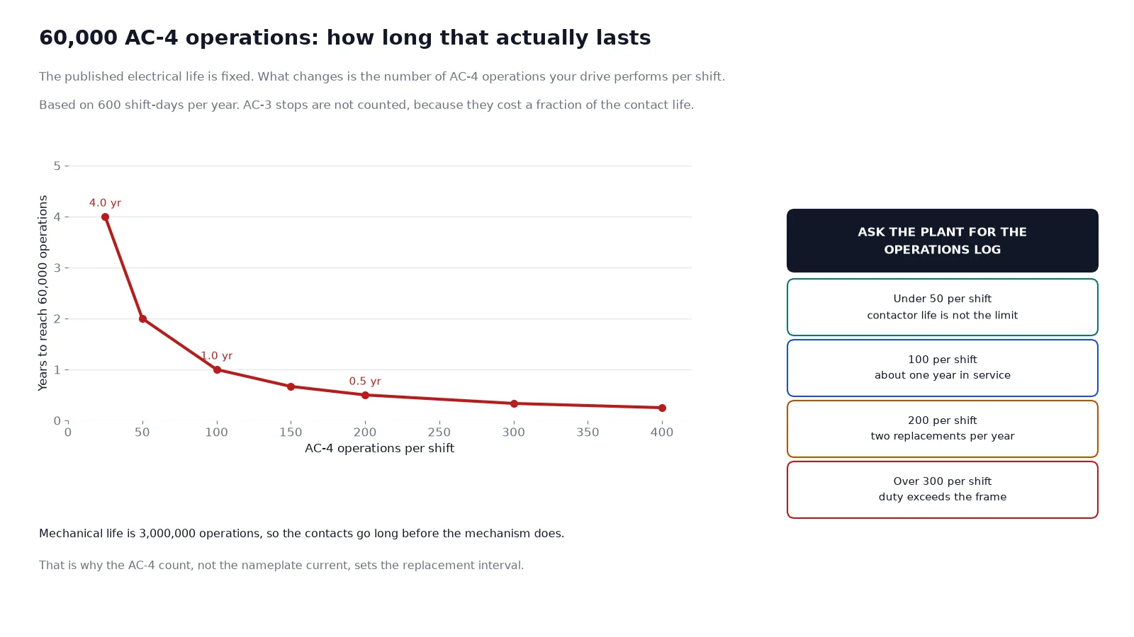
Do the arithmetic before the purchase order, not after the first failure. A drive at 240 AC-4 operations per hour against 60,000 electrical operations gives about 250 hours of continuous worst-case duty. Real mill duty is a mix: a few hundred operations per shift rather than per hour, with AC-3 stops in between. The point is that the published endurance must be compared with the actual operations count from the plant’s logs, and that the number of AC-4 operations per shift is the single most useful figure the maintenance team can supply.
On this frame the control supply is alternating current, but the operating coil is direct current, produced by a rectifier bridge inside the contactor. Once the armature has pulled in, a current-limiting resistor is switched into the coil circuit. Three practical consequences follow.
The buyer’s consequence is that the control voltage is a specification item, not an accessory. The rectifier bridge is built for one control voltage, so a frame ordered for 220 V AC will not accept a 380 V AC supply without a change of bridge. Confirm the plant control voltage before the order, and confirm whether it is AC or DC; the coil voltage and control wiring guide covers the coil options and the pick-up band in detail.
The three-pole frame is the standard choice for a three-phase motor. The single-pole version exists for circuits that genuinely switch one pole: single-phase furnaces, resistor banks, some electrode control circuits and certain DC-link arrangements in older drives. It shares the environmental envelope and the mechanical life with the three-pole version but is not a substitute for it, and using three single-pole frames to build a three-phase starter adds three times the control wiring and three times the interlock logic for no benefit.
Both versions are covered on the GKJ5 three-pole page and the GKJ5 single-pole page. Where the load is between 630 A and 800 A, the CKJ20 frame does the same job in a horizontal layout at 660 V and 1,140 V.
At 1,140 V a 1,000 A contactor corresponds to a three-phase apparent power of about 1,975 kVA, which at a typical mill motor power factor and efficiency lands near 1,500 kW of shaft output. Treat the table below as a starting band, then confirm against the motor nameplate and the duty.
| Motor shaft rating at 1,140 V | Typical full-load current | Frame |
|---|---|---|
| up to about 750 kW | up to about 500 A | 630 A horizontal frame |
| about 750 to 1,100 kW | about 500 to 750 A | 800 A horizontal frame |
| about 1,100 to 1,500 kW | about 750 to 1,000 A | 1,000 A vertical frame |
| about 1,500 to 1,900 kW | about 1,000 to 1,250 A | 1,250 A vertical frame |
Two corrections apply on mill duty. If the motor is a high-slip or high-starting-torque design, the starting current runs above the standard multiple and the frame moves up a size. If the ambient inside the cubicle exceeds the rated 40 degrees Celsius, which is normal in a mill electrical room in summer, the frame moves up a size again or the cubicle needs forced ventilation. Neither correction is optional, and both are cheaper than a summer of tripping.
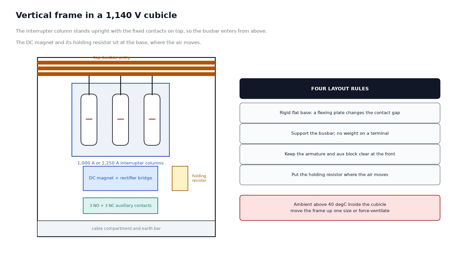
The vertical frame puts the interrupter column upright with the fixed contacts on top, which suits a tall cubicle and a top busbar entry. Four layout rules come out of that geometry.
The vacuum bottle removes the arc chute from the maintenance list, but it does not remove maintenance. Four checks repay their time.
| Check | Interval | What it catches |
|---|---|---|
| Contact resistance per pole | Every major overhaul, and after any suspected fault | Bottle erosion and terminal heating |
| Contact gap and overtravel | Annually, and after any mechanical work on the base | A frame distorted by a flexing plate or an over-torqued terminal |
| Coil resistance and rectifier output | Annually | A failing diode or a resistor that is drifting, before it becomes a no-close |
| Thermography of main terminals | Six months, and after commissioning | Loose lugs, which are the most common cause of a burnt terminal in a dusty plant |
Cleaning matters more here than on a general-purpose starter. Scale dust is conductive when damp, and it settles on the exposed insulation between the bottle and the frame. A dry compressed-air clean at each overhaul, with the cubicle isolated, is the cheapest life extension available.
Six items settle the order: motor shaft rating and full-load current, main-circuit voltage (660 V or 1,140 V), control voltage and whether AC or DC, the AC-4 operations per shift, ambient temperature inside the cubicle, and whether a mechanical latch is required. Add the fault level at the bus so the upstream protection can be confirmed, and state whether the frame is going into a new cubicle or replacing an existing one, because the adapter arrangement is easier to design at the quotation stage than afterwards.
If the duty figures are uncertain, send the plant’s operations log for one representative week. A contactor chosen against a real operations count lasts; one chosen against a nominal current figure becomes a recurring line item in the maintenance budget.
Switching large low-voltage motors and similar heavy loads at 660 V or 1,140 V, typically in steel mills, rolling lines, mines and heavy process plants, where the drive starts and stops often and the switching duty is AC-4 rather than AC-3.
A vertical column suits tall cubicles with a top busbar entry and gives the armature a clean vertical travel. The horizontal layout exists for shallow drawers and low-profile starters, where the same ratings will not fit vertically.
The insulation is built for the higher voltage, so 400 V operation is electrically safe, but the frame is physically large for the current and a smaller device is usually the better economic choice. Match the frame to the system, not just to the amps.
The published electrical life is more than 60,000 AC-4 operations, with three million mechanical. Divide 60,000 by the actual AC-4 operations per shift from your log to get the replacement interval, and treat any figure derived from an AC-3 rating as optimistic.
An AC control supply, converted internally to DC by a rectifier bridge, with a current-limiting resistor switched in after pull-in. The control voltage is fixed at order, so confirm it before the purchase order rather than after delivery.
No. The bridge produces the DC the coil needs from the AC control supply. If the plant prefers to feed a DC control bus directly, order the coil wound for that DC voltage instead, and skip the bridge.
Mill duty rewards a specification written from the operations log rather than from the nameplate. Send the motor data, the switching duty, the control voltage and the cubicle ambient, and the frame can be matched to the drive, the DC magnet built for the control supply, and the adapter arrangement designed before the first contactor fails. Where the drive is being converted from an older air-break frame rather than installed new, the CJ12 retrofit guide covers the mounting plate, the terminal spacing and the overvoltage question. Send the drive data to our engineers and the frame is confirmed against the duty.