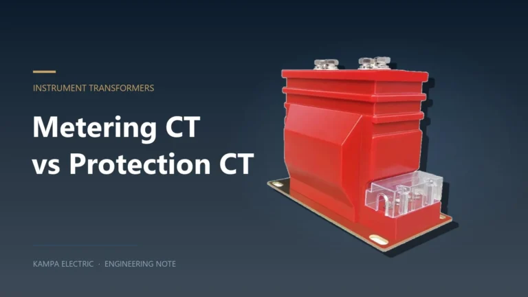
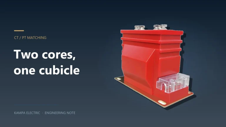
A combined instrument transformer exists because a ring main unit has no room. A conventional 12 kV RMU metering scheme needs three current transformers around the cable cores and two or three voltage transformers fed from the busbar, each with its own primary connections, its own fuses and its own secondary wiring. A combined unit puts all of it into one cast resin body: CT cores around the primary conductors, PT windings fed from the same insulation structure, and a single secondary terminal chamber that the utility can seal.
The trade is real and worth understanding before the tender goes out. You gain footprint, fewer primary joints, one insulation system and a metering module that arrives pre-wired and factory-tested. You lose flexibility — a ratio change or a failed winding means replacing the whole unit — and you take on a single point of failure in a revenue circuit. This guide covers what a combined unit actually is under IEC 61869-4 combined instrument transformers, where it sits inside an RMU, the ratings that define it, and the specification items that decide whether it bills accurately for twenty years or becomes a dispute in year two.
What “combined” means in the standard
A combined transformer is a single unit in which the current transformer and the voltage transformer share one enclosure, one insulation system and one set of primary terminals. The construction standard is IEC 61869-4, “Additional requirements for combined transformers”, which sits on top of the general requirements in IEC 61869-1, the CT requirements in IEC 61869-2 and the PT requirements in IEC 61869-3. In Chinese practice the equivalent chain is GB/T 20840.1 through GB/T 20840.4, and the 2015 edition of part 4 replaced the older GB 17201 combined-transformer standard — a distinction worth checking in older tender documents, because some still cite GB 17201.
Members of the JLSZV family are the type most often seen in 10 kV distribution: two single-phase PT elements and two CT cores in one cast or oil-filled body, connected in V/V so that two measuring elements cover a three-phase, three-wire system. The designation decomposes usefully — J for combined, L for current, S for three-phase, Z for cast resin (or oil, depending on the suffix), and 10 for the voltage class.
Two-element V/V or full three-phase
The first structural decision is how many phases are measured. It changes the accuracy of the energy calculation, the secondary wiring, and the price.
| Arrangement |
Elements |
What it measures |
Where it fits |
| Two-element V/V |
2 CT + 2 PT |
Three-phase three-wire active and reactive energy; assumes balanced or at least calculable conditions |
Most 10 kV distribution metering in Asia; compact RMUs |
| Full three-phase |
3 CT + 3 PT |
Independent per-phase measurement; supports unbalance and single-phase loads |
Utility smart metering modules, feeders with mixed single-phase load |
| Three CT, two PT |
3 CT + 2 PT |
Per-phase current, two-element voltage |
Where current is needed for a relay but voltage only for billing |
V/V is not a compromise on accuracy for a three-wire system — it is the mathematically correct minimum number of elements, and two-element metering is standard practice on 10 kV distribution feeders throughout the region. It stops being adequate when the neutral carries current, which is why a four-wire LV-side or a heavily unbalanced MV feeder moves to full three-phase measurement.
Where the unit sits inside an RMU
An RMU is described in shorthand by its functional units — C for a load-break ring switch, V for a vacuum circuit breaker way, F for a fused transformer feeder. A C-C-V unit has two ring ways and one breaker way. Metering is not part of that shorthand, which is exactly where specifications go wrong: the letters describe switching, not measurement.
In practice the combined unit lands in one of three places:
- A dedicated metering cubicle. Three CTs and three PTs in their own compartment, with the meter box alongside. This is the arrangement most utility specifications ask for on a smart or tariff-metered RMU, and it keeps the revenue circuit physically separate from the protection circuit.
- Block CTs in the breaker way, PTs in a separate compartment. Common when the same CTs serve both the relay and the meter, and when voltage is only needed for the billing element.
- Ring-core CTs or current sensors around the cable. The smallest option. A ring-core CT is rated at 0.72 kV / 3 kV for one minute rather than at full system insulation, because the cable screen and the earthed body do the insulation work. Current sensors to IEC 60044-8 go further and deliver a low-level signal instead of 5 A or 1 A.
Whatever the arrangement, the compartment also needs the voltage presence indication. VPIS to IEC 62271-206 or a VDS to IEC 61243-5 takes its signal from capacitive dividers in the bushings, and on a metered RMU it is usually the same divider chain that feeds the voltage sensing input to the meter box. Specify it in the same clause, because retrofitting indication into a sealed compartment is not practical.
The ratings that actually define the unit
A combined unit is specified by a short list of numbers, and most of them are fixed by the network rather than by preference. The figures below are typical for a 10 kV class unit and should be read as a shape, not a quotation.
| Parameter |
Typical value, 10 kV class |
What it controls |
| Rated voltage / highest voltage for equipment |
10 kV / 12 kV |
Voltage class and matching to the RMU |
| Rated voltage ratio |
10000/100 V, or 10000/√3 : 100/√3 V |
Whether the meter reads phase-to-phase or phase-to-neutral |
| Rated primary current |
5 A to 600 A, in standard steps |
Load range and low-load accuracy |
| Rated secondary current |
5 A or 1 A |
Lead burden and meter compatibility |
| Accuracy class |
0.2S, 0.5S, 0.2, 0.5 |
Billing grade; S classes for wide load swings |
| PT rated output |
20–30 VA per phase |
Number of meters and transducers fed |
| CT rated output |
10–20 VA per core |
Meter plus lead loop |
| Insulation level |
12 / 42 / 75 kV |
Power frequency withstand 42 kV 1 min, lightning impulse 75 kV |
| Short-time thermal current |
100 × I1n for 1 s |
Survival of a through-fault |
| Rated dynamic current |
250 × I1n |
Peak electromagnetic force |
| Creepage distance |
≈340 mm |
Pollution performance, indoor or outdoor |
Two of those rows do the most damage when they are wrong. The voltage ratio decides whether the meter’s phase angle reference is correct — a 10000/100 unit in a system designed for 10000/√3 : 100/√3 reads √3 times high on every phase voltage and the energy register is wrong by the same factor. The accuracy class decides whether the reading is defensible: 0.5 is a commercial grade, 0.2S is a tariff grade, and a utility revenue meter behind a 0.5 class unit will be queried at the first audit.
Accuracy and burden: the part that is usually under-planned
A combined unit concentrates both metering circuits in one terminal chamber, which makes burden planning more important rather than less. Three things share the same secondary circuits: the meter, the test terminal block with its links, and the wiring between them. On a 5 A secondary, burden in VA is 25 times the loop resistance — so a 20 m run of 2.5 mm² copper loop already costs around 7 VA before the meter draws anything.
Against a 10 VA CT core, that is most of the budget. The usual outcomes are a core operated beyond its rated burden (accuracy class no longer guaranteed) or a specification quietly upgraded to 15 or 20 VA. Neither is expensive; what is expensive is discovering it after the meter reads low for six months.
The same arithmetic does not apply to the PT side in the same way. Voltage transformers are not burdened by lead resistance in VA terms; the cable shows up as a voltage drop and therefore as a ratio error. On a 1.5 mm² run of 40 m feeding a 20 VA burden the additional ratio error is on the order of 0.1%, rising to about 0.23% at 50 VA. That is tolerable on a 0.5 class but marginal on a 0.2 class, which is why revenue PT circuits use short runs and generous conductor size.
Combined unit or separate CT and PT
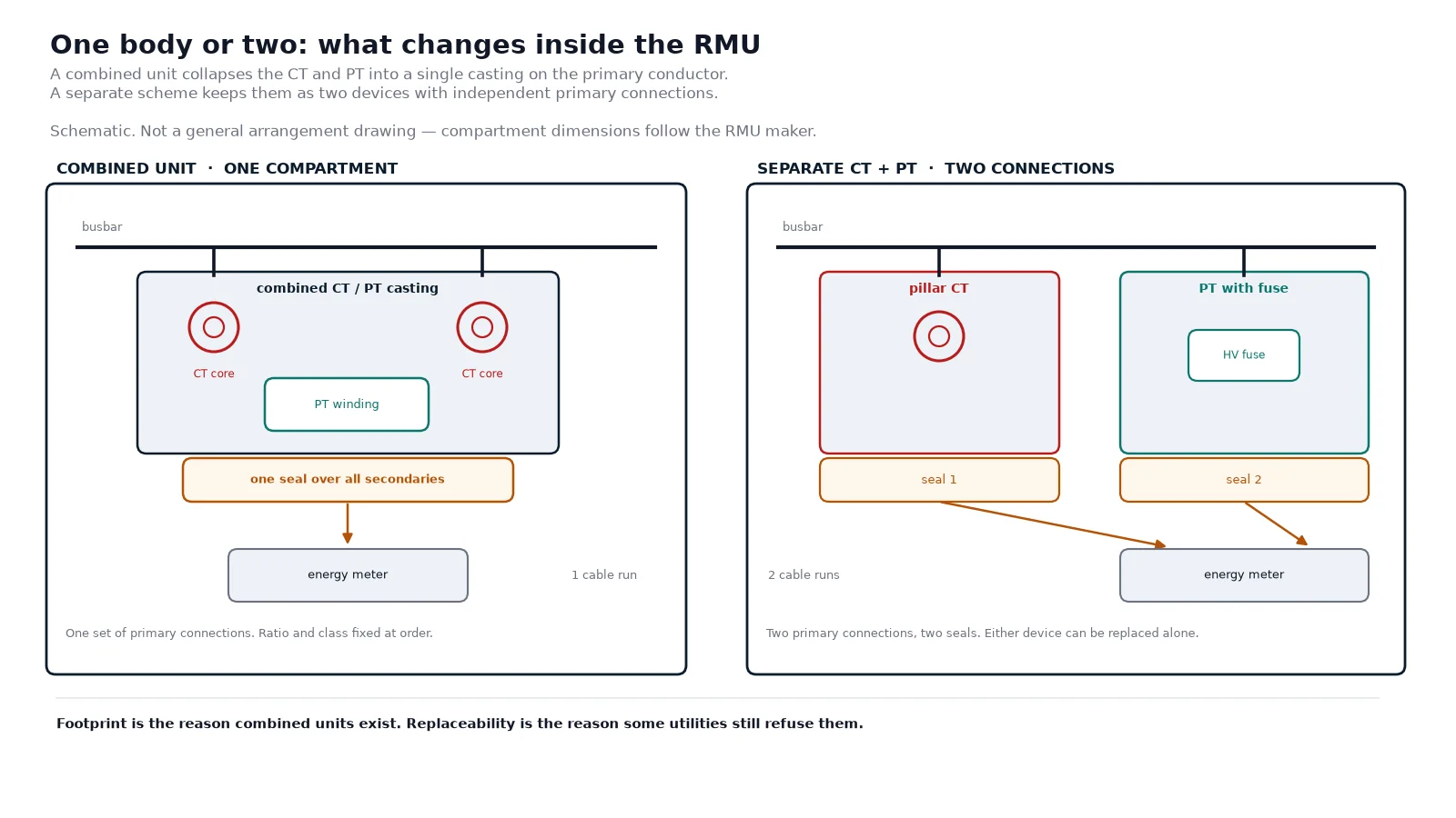
The decision is usually made for you by the RMU design, but it is worth making deliberately. Where a project uses separate units instead, the same measurement job can be built from a 10 kV pillar-type current transformer in the breaker or cable compartment and a fused voltage transformer fed from the busbar.
| Criterion |
Combined unit |
Separate CT + PT |
| Footprint in the RMU |
One body, one compartment |
Two locations, two sets of primary connections |
| Primary connections |
One set, factory-made |
Separate joints for CT and PT |
| Ratio flexibility after order |
Fixed; replace the unit |
Change one device only |
| Failure consequence |
Whole metering unit out of service |
Only the failed device |
| Spares holding |
One part number, higher value |
Two part numbers, lower value each |
| Anti-tamper |
Single sealed terminal chamber |
Two chambers, two seals |
| PT fusing |
Internal or in a shared compartment |
Accessible HRC fuse per PT |
| Lead time |
Longer; built to order |
Often ex-stock |
Where the metering is the utility’s revenue boundary, the combined unit usually wins on sealing and on the single set of primary connections. Where the metering is a check meter or an internal energy allocation, separate devices are easier to maintain and cheaper to replace. A middle path that appears in many specifications: a combined unit for the billing element, plus a separate protection CT in the breaker way so the relay does not depend on the revenue device.
The anti-tamper argument
One sealed chamber is a real advantage. A combined unit brings all secondaries to a single terminal area with a lead-sealable cover, and the better indoor frames go further — the LZZBJ12-10 frame shields the secondary outlet with three possible exit directions and closes the shield over the wiring so the circuit cannot be tapped without disturbing the seal. On a revenue boundary that is worth more than the footprint saving.
Insulation, pollution and the outdoor variants
The indoor and outdoor versions of the same combined unit are not the same product with a longer creepage. An outdoor unit carries a rain shed profile, RTV-coated surfaces for hydrophobicity, UV-stable resin, and a creepage specific to the pollution level — the W suffix in JLSZV-10W marks the outdoor variant, typically with a creepage of 31 mm/kV or better for class IV pollution. An indoor unit at 340 mm total creepage is adequate inside a substation building and inadequate on a pole in a coastal industrial area.
Altitude is the other environmental trap. Most published ratings assume 1000 m, and above that the power frequency withstand has to be derated — a common rule of thumb is 1% per 100 m above 1000 m. On a 12 kV unit with 42 kV withstand, 2500 m of altitude removes roughly 15% of the margin.
Ferroresonance is a metering-unit problem too
A combined unit puts PT windings directly on a busbar that is switched by load-break switches, often with a cable on the other side. That is the classic ferroresonance circuit: a saturable inductance in series or parallel with cable capacitance, excited by an uneven break. Normal PT primary current is well under 10 mA; during ferroresonance it reaches amperes, three orders of magnitude higher, and the resulting overvoltage destroys windings and arresters.
Three defences are used in practice: a damping resistor across the broken delta winding, sized by the classical relationship R = 100 × La / N² with La in mH, with the resistor power taken as roughly 50% of one PT’s rated VA; a non-linear silicon carbide resistor at the primary neutral, which sits at high impedance normally and low impedance when the neutral shifts; and a three-phase primary connection in delta, which removes the path entirely but also removes earth-fault detection. The PT fuse and ferroresonance guide works through the sizing, and the reason it belongs in a combined-unit article is that the damping resistor or the neutral resistor has to be specified with the unit, not added afterwards.
What goes into the inquiry
A combined unit is built to order, so the inquiry is effectively the design. These are the items that, if missing, come back as a clarification round or as a wrong unit.
| Item |
What to state |
| System |
Rated voltage, highest voltage for equipment, frequency, neutral treatment |
| Arrangement |
Two-element V/V or full three-phase; number of CT and PT elements |
| Voltage ratio |
10000/100 or 10000/√3 : 100/√3, plus the residual voltage winding if earth-fault detection is required |
| Current ratio |
Primary and secondary, with the expected load range rather than only the maximum |
| Accuracy |
Class per element, plus the instrument security factor on the metering core |
| Burden |
Actual VA per core, including the lead loop and test links |
| Short-circuit duty |
Thermal current and duration, dynamic peak, matched to the RMU fault level |
| Insulation |
Power frequency withstand, BIL, creepage, pollution class, indoor or outdoor |
| Environmental |
Ambient range, altitude, humidity, coastal or industrial atmosphere |
| Mechanical |
Mounting orientation, primary conductor size and termination type, compartment dimensions |
| Secondary |
Terminal arrangement, test links, shorting facilities, sealable cover, wiring diagram numbering |
| Documentation |
Type test reports, routine test certificate, excitation curves for each core |
The compartment dimensions deserve their own line because a combined unit is a large object. A 10 kV three-element unit with 340 mm creepage will not fit a compartment designed around a pair of block CTs, and discovering that at installation is a schedule problem rather than a technical one.
Factory tests and commissioning checks
Routine tests on a combined unit cover the CT elements and the PT elements separately, then the assembly. Expect ratio and polarity on every core, secondary winding resistance, power frequency withstand on the primary and between circuits, partial discharge where the specification calls for it, and an excitation or knee-point check on each core. Where the unit includes a primary fuse, the fuse is part of the routine test — including the continuity check that catches a fuse fitted but not seated.
At commissioning, four checks catch most of the problems that survive the factory: CT polarity against the meter’s phase rotation, PT phase sequence and the broken-delta connection if fitted, burden measurement on the installed loop rather than the design figure, and a primary injection test through the whole metering chain where the utility permits it. The instrument transformer test sequence sets out the full list, and the CT and PT matching guide covers the ratio and phase relationship between the two halves of a metering set.
One distinction that matters when comparing units: a combined metering unit carries only measuring cores, while the CT in a breaker way carries a protection core as well. If the project asks for protection from the same device, the class has to change from 0.5 to something like 5P10 or 5P20, and the core cross-section grows with it. The metering versus protection CT comparison explains why those two cores cannot be the same core — and why a combined unit quoted as “0.5 class” cannot be assumed to have a protection element inside.
Frequently asked questions
What is a combined instrument transformer?
A single unit containing both current transformer cores and voltage transformer windings in one enclosure and one insulation system, built to IEC 61869-4. It delivers CT and PT secondary outputs from one set of primary terminals, which is what makes it practical inside a compact ring main unit.
Which standard applies to a combined metering unit?
IEC 61869-4 for the combined requirements, supported by IEC 61869-1, -2 and -3. In China the equivalent is GB/T 20840.4-2015, which replaced the older GB 17201 standard. Tender documents citing GB 17201 are out of date but still appear.
Why do most 10 kV units use two CTs and two PTs?
Because a three-phase three-wire system can be measured with two elements using V/V connection. It is the minimum correct arrangement, not a cheaper approximation. Systems with a loaded neutral need full three-phase measurement.
Can a combined unit feed both the meter and the protection relay?
Only if it is specified with a protection core. A metering unit normally carries 0.2S or 0.5 class cores, which saturate by design through the instrument security factor. Protection needs a 5P or 10P core, and that has to be written into the order.
What accuracy class should a revenue metering unit have?
0.2S is the usual answer for a tariff boundary, because it holds ±0.2% across 20–120% of rated current and stays inside ±0.75% down to 1%. Class 0.5S is acceptable for commercial billing; plain 0.5 is a monitoring grade, not a revenue grade.
Do combined units need ferroresonance protection?
On a switched busbar with cable capacitance, yes — the PT windings present exactly the saturable inductance that produces ferroresonance. A damping resistor across the broken delta, or a non-linear resistor at the primary neutral, should be specified with the unit rather than retrofitted.
Getting the specification right the first time
A combined metering unit is a good answer to a real constraint: an RMU has a small compartment, a utility wants a sealed revenue boundary, and nobody wants three separate primary connections inside a sealed gas or vacuum enclosure. But the unit is built to order, which means the accuracy class, the voltage ratio, the burden and the ferroresonance provision are all locked in at the moment the casting is poured.
Four numbers decide whether it works: the voltage ratio matching the system’s phase reference, the current ratio matching the real load range rather than the cable rating, the accuracy class matching the billing grade, and the burden matching the actual installed loop. Everything else — creepage, IP rating, terminal arrangement — is a matter of matching the environment, and is easier to correct on paper than on site. For projects assembling an RMU metering module from separate devices instead, the switchgear and substation solutions overview sets out how the CT, PT and switchgear choices interlock.