A metering CT vs protection CT comparison usually starts in the wrong place — with the accuracy class. The class is the last thing that differs, not the first. Both units sit on the same primary conductor, both step current down to 5 A or 1 A, and both are tested to IEC 61869-2 instrument transformers. What separates them is a single design decision: one core is built to stay honest at 5% load, the other is built to stay honest at twenty times rated current. Those two requirements cannot be met by the same piece of iron.
This matters in procurement because the two classes look interchangeable on a datasheet. A 600/5 CT is a 600/5 CT until you read the second line. Fit a metering core where the relay expects a protection core and the relay under-reaches on a fault it should have cleared; fit a protection core into a billing circuit and the meter keeps working, but the energy register drifts and nobody notices for a year. This guide sets out what actually changes — core, class, saturation behaviour, burden, and the tests that prove it — and where the boundary sits between a percentage class like 5P20 and a knee-point class like PX.
The short answer: two cores, two questions
A metering core answers how much current is flowing, to within a fraction of a percent. A protection core answers how much current is flowing, even when it is enormous, without lying about the magnitude. Accuracy in the first case is a revenue question. In the second case it is a safety question, and a few percent of error is acceptable as long as the core does not collapse.
| What changes |
Metering core |
Protection core |
| Question it answers |
Accurate magnitude at normal load |
Faithful magnitude during a fault |
| Standard classes (IEC) |
0.1, 0.2, 0.2S, 0.5, 0.5S, 1 |
5P, 10P, PX, PXR |
| Accuracy stated |
Ratio and phase error at 5–120% of rated current (1% upward for S classes) |
Composite error at the accuracy limit factor |
| Saturation |
Deliberate and early, capped by the instrument security factor |
Avoided up to at least the accuracy limit factor |
| Typical rated burden |
5–15 VA |
10–30 VA |
| Core cross-section |
Small, high-permeability material |
Large, grain-oriented silicon steel |
| What a mix-up causes |
Billing error, damaged meter |
Relay under-reach, failed trip |
Why the two cores cannot be the same core
A current transformer is accurate only while its core stays out of saturation. Every core has a flux limit, and the flux is driven by the secondary e.m.f. needed to push current through the connected burden. Push the primary current high enough and the required e.m.f. exceeds what the core can sustain; the core saturates, the secondary current stops tracking the primary, and the output waveform flattens into a distorted version of reality.
Now consider the two jobs. The metering core spends its life at 20–80% of rated current and needs its best accuracy there, so it is built with a small, high-permeability core that saturates relatively early. That early saturation is not a defect — it is the mechanism that protects the meter from a 20 kA fault. The protection core needs to reproduce a fault current ten or twenty times rated current, so it is built with two to three times the cross-section, which pushes the saturation point far above any current that will ever flow.
Trying to do both in one core means either a metering core that saturates before the relay’s setting, or a protection core whose low-load accuracy is far too coarse for a tariff meter. That is why dual-core construction is normal practice: one casting, two independent magnetic circuits, one metering class and one protection class on the same nameplate. The standard LZZBJ9-10 10 kV pillar CT is a useful example — its published combinations run 0.2/0.5, 0.2S/0.2, 0.5/10P10 and 0.2S/10P10, all in a single cast body with 10/10 VA or 10/15 VA outputs.
Accuracy classes: decimal for metering, P for protection
The decimal classes measure ratio error and phase displacement at defined points of rated current. The P classes measure composite error — ratio error, phase error and waveform distortion combined — at a multiple of rated current.
| Class |
Limit |
Where the limit applies |
Typical use |
| 0.1 |
±0.1% |
5–120% of rated current |
Calibration benches, test labs |
| 0.2 |
±0.2% |
5–120% of rated current |
Precision industrial metering |
| 0.2S |
±0.2% at 20–120%, ±0.75% at 1% |
From 1% of rated current |
Utility revenue metering |
| 0.5 |
±0.5% |
5–120% of rated current |
Sub-metering, panel instruments |
| 0.5S |
±0.5% at 20–120%, ±1.5% at 1% |
From 1% of rated current |
Commercial billing with low night load |
| 5P10 |
≤5% composite error at 10 × In |
Up to the accuracy limit factor |
Overcurrent and earth-fault relays |
| 5P20 |
≤5% composite error at 20 × In |
Up to the accuracy limit factor |
Differential, high fault level feeders |
| 10P10 |
≤10% composite error at 10 × In |
Up to the accuracy limit factor |
Thermal alarms, non-critical indication |
| PX |
Vk, Rct, Imag stated |
Defined by the excitation curve |
High-impedance differential, REF |
The S suffix is about the bottom of the range
A plain class 0.5 CT is only specified from 5% of rated current upward. Below that, the standard says nothing, and in practice the error grows quickly. On a feeder that runs at 8% of the CT ratio overnight and 60% at midday, the overnight hours are being measured by a device that has left its accuracy band — and in a substation with a 600/5 CT the 5% floor is 30 A, which a lightly loaded distribution feeder spends most of its life below.
The S classes fix this by extending the specified range down to 1% of rated current. The cost is a more expensive core and a longer test sequence, which is why 0.2S is specified where the tariff depends on the reading and 0.5 is specified everywhere the reading is only for information. If a tender says “class 0.5, revenue metering”, the correct answer is usually a question: do you mean 0.5, or 0.5S?
The metering core is supposed to saturate
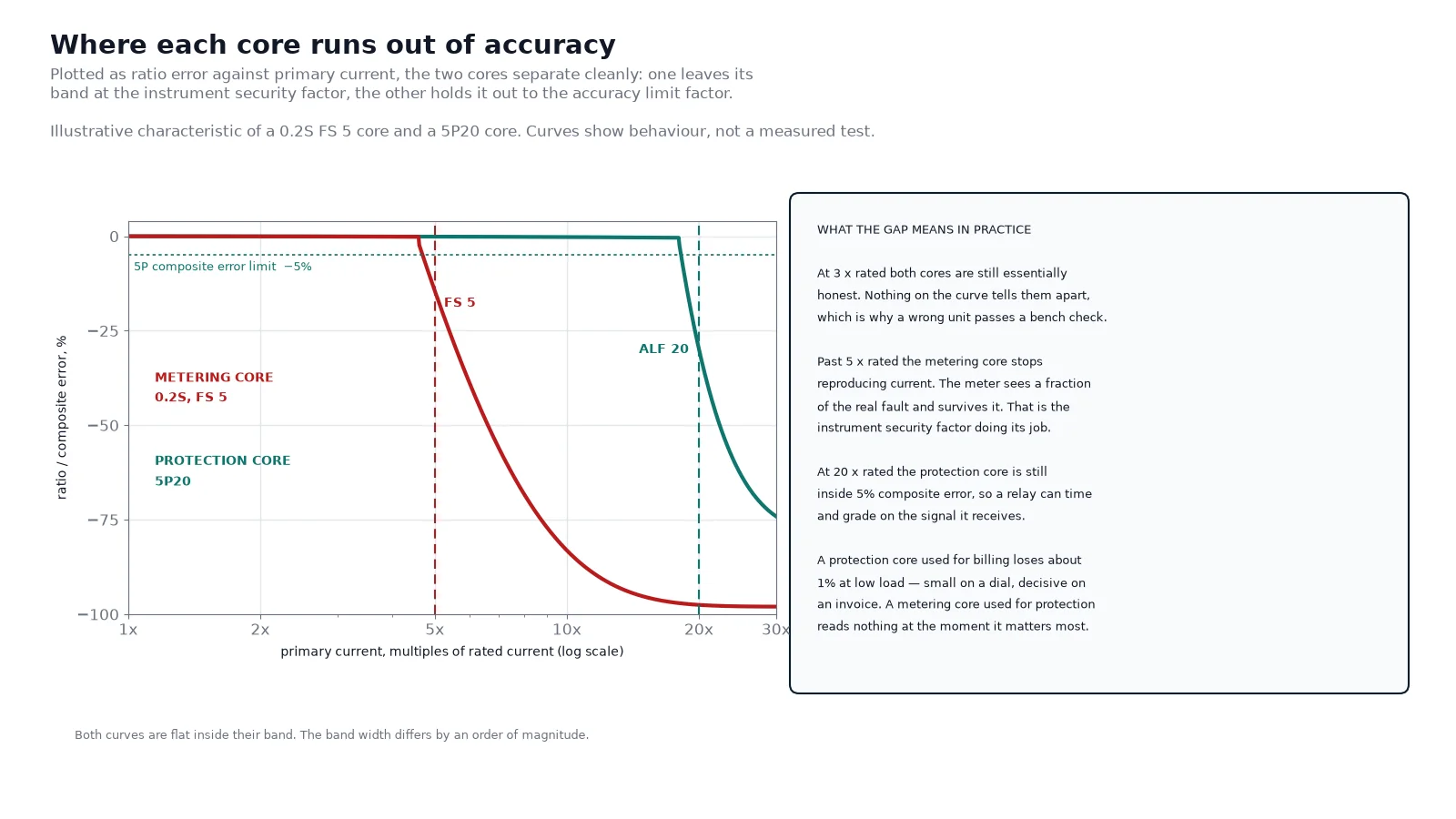
Every metering CT carries a second rating that is routinely omitted from the inquiry: the instrument security factor, or FS. It is the multiple of rated primary current at which the composite error reaches 10%, and it caps how much current the core can push into the meter during a fault. FS 5 and FS 10 are the common values.
The logic is thermal. A meter movement or a solid-state meter input is designed for a few times rated current, not for twenty. If the CT faithfully reproduced a 20 kA fault into a 5 A secondary, the meter would be destroyed along with the test terminal block. An FS 5 core stops reproducing current properly at five times rated, which limits the secondary current to something the meter can survive.
A metering CT specified without an FS limit is therefore a hazard to the instruments downstream, and it is one of the most common omissions in a locally written specification. Write it as part of the class line — “0.2S, FS 5, 10 VA” — not as a separate note that a quotation can quietly drop.
The protection core must not saturate
The protection core has the mirror-image rating. In “5P20”, the 5 is the composite error limit in percent, the P marks a protection class, and the 20 is the accuracy limit factor — the multiple of rated current up to which that 5% limit holds. A 5P10 core is guaranteed to 10 × In, a 5P20 to 20 × In.
The number that gets undersized is the ALF. It must be chosen against the maximum fault current the relay has to see and grade on, not against habit. If the fault level at the busbar is 25 kA and the CT ratio is 400/5, the fault is 62.5 times rated current. A 5P20 core saturates long before that, the secondary current collapses, and a relay set to pick up an instantaneous element at 15 × In may never see the current clearly enough to trip.
The ALF on the nameplate is only valid at rated burden
This is the part that catches people in the field. The declared ALF assumes the core is loaded to its rated VA. Change the burden and the effective ALF moves, roughly in inverse proportion: a 5P10 core loaded at half its rated burden behaves closer to 5P20, and the same core loaded at twice its rated burden behaves closer to 5P5. A relay that was stable in the factory test can under-reach on site because somebody added a second meter to the same core and doubled the loop resistance.
The practical rule is to size the burden from the actual circuit — relay coil, meter, terminal blocks, and the lead loop — and leave margin. A protection core running at 50–70% of its rated VA keeps most of its declared ALF in reserve.
What physically changes inside the unit
- Core cross-section. The protection core is markedly larger for the same ratio, because saturation flux is a function of area. This is why a 5P20 unit is taller and heavier than a 0.5 class unit of the same ratio.
- Core material and treatment. Metering cores use high-permeability material and often a small air gap to stabilise accuracy; protection cores use grain-oriented silicon steel with a gapless or low-leakage design. Annealing after stamping matters more than buyers expect — stress left in the core raises no-load loss and makes ratio error drift with age, so a metering core built from untreated laminations reads low after a few years.
- Number of cores. One casting can hold two or three independent cores: a metering core, a measuring core for the panel meter, and a protection core for the relay.
- Secondary screening. On units intended for revenue circuits, the secondary outlet is often shielded — the LZZBJ12-10 frame closes a shield over the terminal area with three exit directions, which makes the metering circuit difficult to tap into without disturbing the seal.
- Winding. Copper throughout on both types; the difference is conductor size, because the protection core carries far more secondary current during a fault.
When 5P is not enough: class PX and the knee point
Percentage classes like 5P20 describe what the CT delivers into a burden. They do not describe the shape of the excitation curve, and some schemes depend entirely on that shape. High-impedance differential, restricted earth fault, and generator or busbar differential protection compare CTs on both sides of a zone and require them to behave identically. Those schemes are specified with class PX (IEC), class PS (Indian practice) or class TPS (IEEE).
PX is defined by the core, not by a percentage: a rated knee-point e.m.f. Vk, a maximum exciting current at that voltage, a maximum secondary winding resistance Rct at 75 °C, and a turns ratio held to ±0.25%. There is no rated burden and no ALF, because the protection engineer derives performance from the excitation data.
The knee point itself is defined by a 10/50 rule: the sinusoidal secondary voltage at which a 10% increase in voltage produces a 50% increase in exciting current. Below it the core is linear; above it the output collapses within milliseconds.
Worked example
Take a 1000/1 CT on a 20 kA busbar, with the relay 50 m away on 2.5 mm² copper. The through-fault secondary current is 20 A. The CT winding resistance is 3.0 Ω and the one-way lead resistance is 0.37 Ω, so the loop contributes 0.74 Ω. With a security factor K of 2.0 for a 1 A secondary scheme:
Vk ≥ 2.0 × 20 × (3.0 + 0.74) = 149.6 V
A 150 V knee point is the minimum, and the stabilizing resistor is then calculated from the same terms. Two consequences follow. First, a specification that says only “5P20” cannot be checked against this calculation, because Vk is unknown. Second, if the lead run is longer than assumed, Vk rises with it — which is why the CT on a high-impedance scheme is often the largest item in the switchgear bay.
Burden and lead length decide the accuracy you actually get
At 5 A secondary, burden in VA is 25 times the loop resistance in ohms. The factor of 25 is just I², and it is why 5 A schemes are so sensitive to cable size while 1 A schemes are so forgiving.
| Copper conductor |
Loop resistance, 50 m loop |
Burden at 5 A |
Burden at 1 A |
| 2.5 mm² |
0.70 Ω |
17.5 VA |
0.70 VA |
| 4 mm² |
0.44 Ω |
11.0 VA |
0.44 VA |
| 6 mm² |
0.29 Ω |
7.3 VA |
0.29 VA |
| 10 mm² |
0.18 Ω |
4.4 VA |
0.18 VA |
Read the first row against a 10 VA core. The leads alone consume 17.5 VA before the meter draws anything, which means the core is already operating beyond its rated burden and its accuracy class no longer applies. The same circuit on a 1 A secondary spends 0.70 VA on the leads and has 9 VA left for the instruments. This is the entire argument for 1 A secondaries on long runs, and it is also why a metering CT repeated into a distant control room is often specified at 1 A while the protection core in the same body stays at 5 A.
When the ratio itself is still open, the load side comes first: pick the ratio from the expected load, not from the cable. The CT ratio selection table works through that calculation with worked examples. Once the ratio and burden are fixed, the class follows almost automatically.
Specification matrix by application
The same 600/5 ratio can be specified six different ways depending on what sits behind it. This table is a starting point, not a substitute for the scheme calculation.
| Application |
Metering core |
Protection core |
Notes |
| Utility revenue metering, RMU |
0.2S, FS 5, 5–10 VA |
Not fitted |
Sealed terminal cover, separate metering cubicle |
| Industrial feeder, numeric relay + check meter |
0.5, 10 VA |
5P10, 15 VA |
Two independent cores in one body |
| Transformer differential, low-impedance relay |
0.5, 15 VA |
5P20, 15 VA |
ALF must exceed through-fault current ÷ ratio |
| High-impedance REF or busbar differential |
— |
PX: Vk, Rct, Imag |
Requires the scheme calculation before ordering |
| Motor feeder |
0.5, 10 VA |
10P10, 15 VA |
Start current 5–7 × FLA, plus a DC offset |
| Capacitor bank |
0.5, 10 VA |
5P10, 15 VA |
Check harmonic content before fixing the class |
Five specification mistakes that show up on site
- Using one core for both functions. The meter and the relay need different saturation behaviour. Two cores in one body costs far less than one misapplied core.
- Leaving FS off the metering class. Without it, a fault can put twenty times rated current into a meter input rated for a fraction of that.
- Quoting an ALF without a burden. The declared ALF is conditional on rated VA. A protection core sized to 15 VA, connected to a circuit that draws 25 VA, is no longer a 5P20.
- Specifying 5P20 for a scheme that needs PX. If the protection is high-impedance differential, a percentage class tells the designer nothing usable. Ask for Vk, Rct and Imag.
- Picking the ratio from the cable ampacity. A CT that carries the cable’s rating is running at 15% of its primary on a normal day. Size the ratio to the load, then check the fault level against the ALF.
The tests that separate the two
You can tell a metering core from a protection core at the test bench without opening the casting. The instrument transformer testing sequence covers the full routine list; these are the four that matter for the metering-versus-protection question.
- Excitation (magnetisation) test. Sweep secondary voltage with the primary open and plot exciting current. A metering core bends early; a protection core stays linear well past its ALF; a PX core is judged precisely against its declared Vk and Imag at that voltage.
- Secondary winding resistance. Measured at 75 °C and compared with the declared Rct. This is a PX parameter and also a useful health check on any core.
- Composite error at ALF. The type test that justifies the P class. A routine test at a single point is not a substitute.
- Burden and ratio/polarity check. Confirms the loop is what the design assumed. Polarity errors show up as a differential relay that trips on load, which is the most expensive kind of commissioning fault.
One safety point that belongs in every maintenance procedure: a CT secondary must never be open-circuited while the primary is energised. The open secondary can develop kilovolts, damage the insulation and create an arc-flash hazard. Short the secondary at the CT terminal block before disconnecting anything — and use the test links provided for that purpose.
Matching CTs to the switchgear they sit in
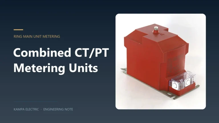
The metering-versus-protection decision does not happen in isolation. In a KYN28 cubicle or a ring main unit, the CT and PT have to fit a compartment, share a primary conductor, and deliver their secondaries to a terminal block that the utility will seal. For projects where the metering and protection cores share a housing with a voltage transformer, the combined CT/PT metering unit for ring main units covers that arrangement and its burden planning.
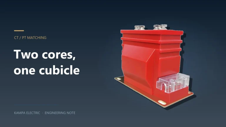
The CT and PT matching guide for KYN28 switchgear and RMUs covers the physical and ratio side of that problem; the class split covered here sets what goes on the nameplate. For the protection scheme itself — overcurrent, earth fault, differential and how the CT classes support each other — the protection coordination guide is the companion read.
For projects where the switchgear, CTs and relays are bought as one package, it also helps to see the whole distribution chain rather than the individual component: the industrial power distribution and protection solutions overview sets the CT duty in the context of the feeder it protects.
Frequently asked questions
Can a protection CT be used for metering?
Technically it will produce a current, but the accuracy class is wrong for billing. A 5P20 core is specified at ±5% composite error, which is an order of magnitude coarser than a 0.5 class, and it has no defined low-load accuracy. Revenue metering with a protection core is a guaranteed dispute at the first meter audit.
Can a metering CT be used for protection?
No. A metering core saturates by design at its instrument security factor — typically 5 to 10 times rated current — which is well below the fault currents a relay has to measure. The relay would see a collapsed secondary current exactly when it needs the true value.
What does 5P20 mean on a CT nameplate?
Composite error of no more than 5% up to 20 times rated primary current, with the core loaded to its rated burden. Both conditions matter: exceeding the rated burden reduces the effective accuracy limit factor.
What is the difference between 0.2 and 0.2S?
Both allow ±0.2% at rated current. A plain 0.2 class is only specified from 5% of rated current upward; 0.2S is specified from 1%, with a ±0.75% limit at that point. The S class is what makes a lightly loaded feeder billable.
Should I specify a 1 A or a 5 A secondary?
Look at the lead loop first. At 5 A, burden in VA is 25 times the loop resistance, so long runs consume the core’s rating before the instruments draw anything. At 1 A the figure is 1 times the loop resistance. Runs beyond roughly 50 m usually justify 1 A secondaries.
How many cores should one CT have?
One per function: a metering core for the tariff meter, a measuring core for the panel instrument or SCADA transducer, and a protection core for each relay scheme. Two cores is the practical minimum on a feeder with both metering and overcurrent protection; three is common on transformer incomers.
What to carry into the inquiry
The choice between a metering CT and a protection CT comes down to four numbers that should be on the inquiry, not left to the supplier: the ratio and the expected load range, the accuracy class with its FS or ALF, the actual burden including the lead loop, and the fault current the protection has to see. Get those four right and the class follows without argument. Get the burden wrong and the class on the nameplate stops being true the moment the panel is wired.
If the scheme includes high-impedance differential, add the fifth item — the Vk calculation — because that decision cannot be recovered after the casting is poured. Send the single-line diagram, the relay models and the lead lengths with the inquiry and the specification can be checked against the actual circuit rather than against a template.