PT fuse selection looks like the simplest task in a medium-voltage cubicle. The transformer draws a few hundred milliamps at most, so a small fuse should protect it, and the smallest standard fuse is already ten times that. That reasoning is exactly how PTs end up with fuses that open on energisation, or fuses that never open at all while the PT behind them cooks.
A voltage transformer primary fuse has two jobs that pull in opposite directions. It must survive the magnetising inrush of a highly inductive, lightly loaded transformer — an inrush that can reach twelve times rated current for a tenth of a second. And it must interrupt a genuine internal fault, in a winding with very little mass to absorb energy, before the insulation is destroyed. Between those two requirements sits a third problem: in unearthed networks, the fuse is often blamed for failures that are not fault current at all. This guide covers the rating, the coordination and the resonance problem that no fuse rating can solve.
What the PT Fuse Actually Protects
The primary fuse on a voltage transformer is not a feeder fuse scaled down. Its scope is narrow and specific:
| Condition |
Who clears it |
Role of the primary PT fuse |
| Secondary overload or short circuit |
Secondary MCB or fuse |
Backup only — should not operate |
| Primary winding internal fault |
Primary fuse |
Primary duty — must operate fast enough to limit damage |
| Magnetising inrush at energisation |
Nobody — it is normal |
Must ride through without melting |
| Sustained ferroresonance |
Sometimes the fuse, usually too late |
Not a designed function; see the resonance section |
That table explains most field confusion. A fuse that trips on a PT is usually responding to a secondary problem, a resonance condition or a genuine winding failure — not to the overload it was nominally installed for. Selecting it correctly means being honest about which of those the fuse can actually handle.
The Two Currents That Set the Rating
Continuous Current: The 300 Percent Rule
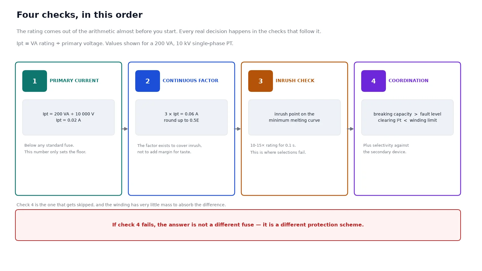
Start from the PT’s rated primary current. It follows directly from the rating plate:
Ipt = VA rating ÷ primary voltage
For a 200 VA single-phase PT on a 10 kV system that is 0.02 A. For a 500 VA unit on the same system, 0.05 A. These are tiny numbers, far below any standard fuse. The fuse is not sized to the load; it is sized to tolerate everything the load legitimately does.
The conventional rule of thumb is to select a fuse rated at roughly 300 percent of the PT primary full-load current, then round up to the next standard size. That factor is not a safety margin in the usual sense — it exists to cover the inrush, and it is a substitute for the real calculation when inrush data is unavailable.
Inrush: The Number That Actually Decides
When a PT is energised at system voltage, the core saturates and the winding draws a magnetising current many times its rated value. Manufacturers express this as a multiple of full-load current and a duration — 10×, 12×, 15×, held for a tenth of a second or so. The fuse must not melt anywhere on that inrush curve.
This is a curve comparison, not a single number. The PT’s inrush point — current multiple against time — is plotted on the fuse’s minimum melting curve. If the point sits below and to the left of the curve, the fuse holds. If it sits on or above it, the fuse opens on energisation, and no amount of re-checking the rule of thumb will explain why, because the rule of thumb was only an approximation of this comparison.
Where the inrush data is available, use it — it is the only method that produces a defensible answer, because it compares the actual inrush point with the actual melting curve. Where it is not, the 300 percent rule is the accepted fallback. Published application guidance also works in a second way: it first fixes a minimum continuous-duty margin of about 1.5× Ipt, then applies the inrush requirement on top, which is what pushes real MV PT selections into the 0.5 to 2 A band rather than down to the arithmetic minimum. All three approaches converge on the same practical conclusion: the answer is one of the smallest standard E-rated fuses, and the selection work is in proving it survives inrush.
The E Rating and What It Guarantees
Medium-voltage PT fuses almost always carry an E rating. The definition is precise and worth knowing, because it is what makes fuses from different manufacturers interchangeable.
An E-rated fuse is a general-purpose current-limiting fuse — capable of interrupting every current from its rated interrupting capacity down to the current that melts the element in one hour. The rating itself is defined by a melting characteristic: the current-responsive element must melt in 300 seconds at a current between 200 and 240 percent of the fuse’s continuous rating. That is the whole basis of interchangeability between brands.
Two consequences follow. First, an “E” marking is not a quality grade or a speed class; it is a defined time-current characteristic. A 1E fuse from one maker and a 1E fuse from another will melt within the specified band, and that is the guarantee. Second, the fuse is designed to give the transformer a chance rather than to protect it precisely: the element on the standard curve melts in minutes at two to three times rating, which is far above a PT’s thermal limit over that period. That is why the E-rated PT fuse is described as primary protection against a winding fault, not as thermal protection for the transformer.
Standard ranges are small. For 7.2 kV PT fuse families, ratings typically run from 1/2E to 3E with an interrupting capacity of around 50 kA symmetrical. For 5 kV families, roughly 1/2E to 5E at the same interrupting level. If your calculated requirement falls outside that band, the answer is not a bigger PT fuse — it is a different protection scheme.
Breaking Capacity and I²t Coordination
Three checks finish the selection, and each one has a failure mode that a rating table cannot show.
Breaking Capacity Against System Fault Level
The fuse’s interrupting rating must exceed the prospective fault current at its point of installation, not the fault level at the substation entrance. On a 10 kV bus with 20 kA of available fault current, a 50 kA PT fuse is comfortable. On a high-energy bus near a large transformer, check, because a fuse applied beyond its interrupting capacity may rupture rather than clear — and it sits inside a small compartment with no venting path.
I²t Against the PT Thermal Limit
This is the check that gets skipped and matters most. The fuse’s total clearing I²t must be below the thermal withstand of the PT primary winding. A small E-rated fuse has a low I²t, which is the good news — but the winding has very little copper and very little thermal mass, so its withstand curve falls steeply. Compare the two curves rather than the two current values: a fuse can be correct on current and still let through more energy than the winding can absorb before the element melts.
Selectivity With Secondary Protection
A secondary short circuit should be cleared by the secondary device, with the primary fuse untouched. Check that the secondary protective device’s total clearing time sits comfortably below the PT fuse’s minimum melting time at the reflected primary current. The margin collapses on small PTs, because the primary current reflected from a secondary fault is small enough that the primary fuse’s melting time stretches into minutes — during which the winding is being cooked by a fault the secondary device should already have cleared.
Where the PT burden and ratio leave little margin, the correct answer is a faster secondary device, not a smaller primary fuse. Reducing the primary fuse to gain selectivity trades a nuisance trip for an inrush trip.
Two Worked Examples
Example one — 800 VA, 2,400 V. Ipt = 800 ÷ 2,400 = 0.333 A. The manufacturer states an inrush of 12× for 0.1 s, so the worst-case inrush point is 12 × 0.333 = 4 A at 0.1 s. On the fuse’s minimum melting curve, a 1E unit holds that point comfortably. The 300 percent rule gives 3 × 0.333 = 1.0 A, which also lands on 1E. Both methods agree: select 1E.
Example two — 200 VA, 10 kV. Ipt = 200 ÷ 10,000 = 0.02 A. Three times that is 0.06 A, which is below the smallest standard rating — the practical floor applies. Here the decision is driven entirely by inrush and by the smallest fuse the manufacturer offers, and the correct answer is the smallest standard E-rated unit that passes the inrush comparison, not a fuse sized to 0.06 A. This is the case where the arithmetic gives a number that does not exist and the application rules take over.
Ratings and burdens feed directly into the ratio and accuracy choice, which is covered in the voltage transformer selection guide. Getting the burden wrong is the most common reason a correctly fused PT still under-performs.
When the Fuse Cannot Help: Ferroresonance
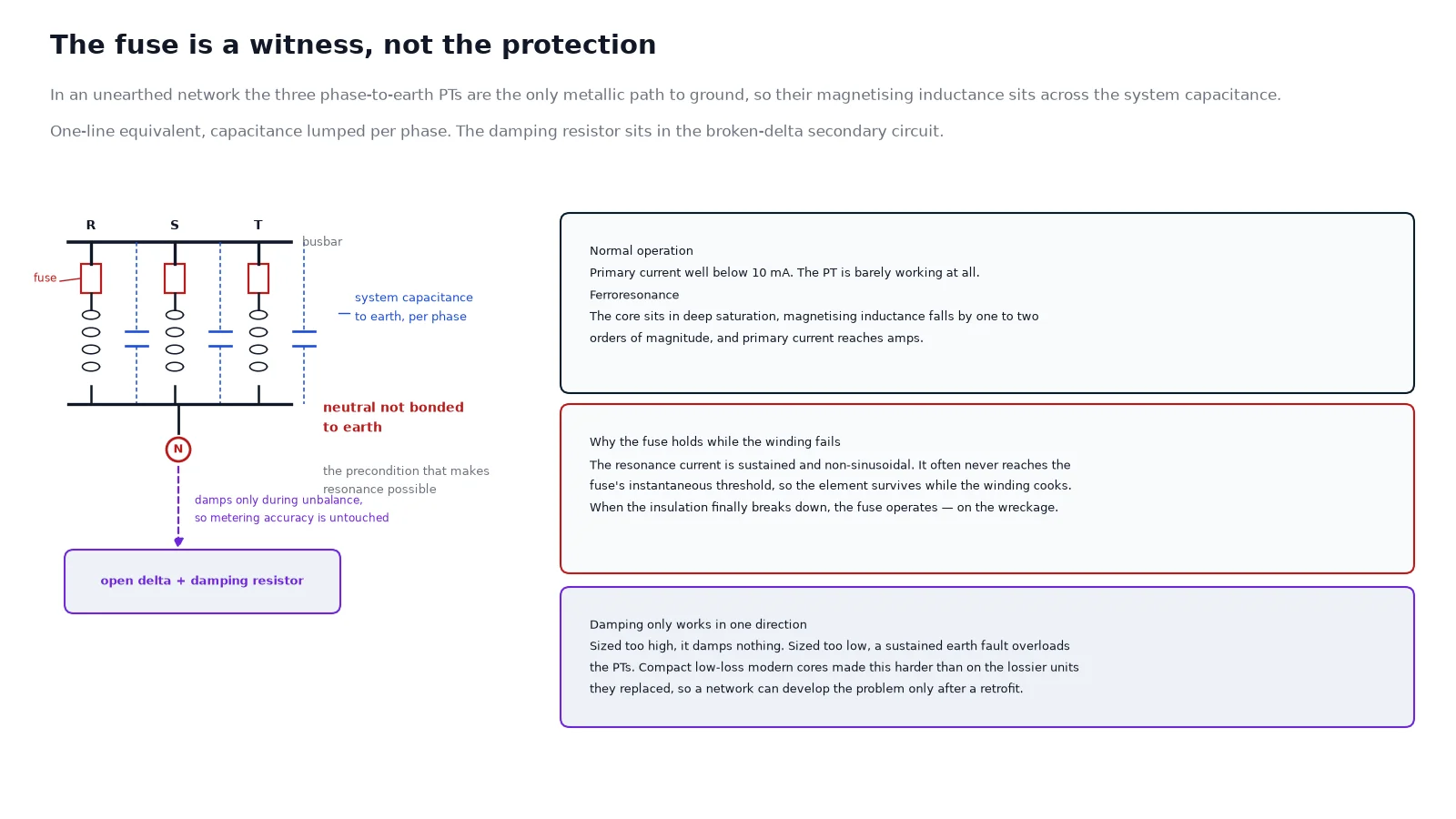
Here is the failure that fills the repair bench. In an unearthed or impedance-earthed medium-voltage network, the three phase-to-earth PTs are the only metallic path from the system to ground. Their magnetising inductance sits in parallel with the system’s capacitance to earth, and that combination is a non-linear resonant circuit. Every switching operation, every fault clearance, every energisation charges and discharges that capacitance through the PT windings.
In normal operation the primary current in an MV voltage transformer is well below 10 mA. Under ferroresonance the core goes into deep saturation — magnetising inductance falls by one to two orders of magnitude — and primary currents reach amps. That is three orders of magnitude above normal, in a winding with no thermal capacity to spare.
Why the Fuse Does Not Save the PT
The resonance current is sustained and non-sinusoidal. It frequently does not reach the instantaneous trip threshold of the primary fuse, so the fuse holds — and the winding fails thermally, or the insulation breaks down and then the fuse operates on the resulting fault. Either way, the fuse is the last witness, not the protection. Blaming the fuse for a burnt PT is diagnosing the symptom.
The mode shapes the damage. Fundamental-frequency ferroresonance produces overvoltages around 1.5 to 2.5 per unit. Subharmonic modes produce severe waveform distortion and can reach higher overvoltages. Quasi-periodic modes are chaotic and unpredictable. All of them look like nothing else on a power quality recorder, which is why field diagnosis depends on capturing the event rather than inspecting the wreckage.
Two preconditions must both hold for it to start: a point in the system whose potential is not fixed — the neutral of an unearthed section — and a transition that drives at least one phase into saturation. Remove either and the phenomenon cannot sustain itself. Solidly earthed systems very rarely experience it, which is the single most useful diagnostic fact in the whole subject.
Why It Is Getting Worse Rather Than Better
Modern PTs are compact and use low-loss core steel. Both trends lower the losses that would otherwise damp the oscillation, and compact geometry raises the capacitance. The result, noted in the application literature, is that damping has become harder on new equipment than on the older, lossier units it replaced. A network that ran for thirty years without a resonance problem can produce one after a switchgear replacement — with the PTs themselves blamed.
Mitigation Options Compared
There is no universally applicable suppression method, and the choice is a trade between damping effectiveness, continuous losses and cost.
| Method |
How it damps |
Strengths |
Costs and limits |
| Damping resistor across the open-delta secondary |
Loads the zero-sequence circuit during unbalance only |
Does not affect metering accuracy in normal operation; low cost |
Less effective on all resonance modes; must be sized so a sustained earth fault does not overload the PT |
| Primary neutral non-linear resistor (resonance eliminator) |
High impedance normally, low impedance when the core saturates; also limits the inrush that blows fuses |
Damps at the source; strong protection against PT burn-out |
Added component in the neutral path; sizing is model-specific |
| Resistors across each phase secondary |
Permanent damping load |
Simple to retrofit |
Absorbs power continuously and shifts metering accuracy |
| Anti-resonance PT design |
Core designed to saturate well above system voltage |
Removes the problem at the source |
Cost premium, and accuracy class may be reduced |
| Delta-connected primary |
No neutral path, so no zero-sequence resonance circuit |
Eliminates the mechanism completely |
Loses the ability to detect earth faults — usually unacceptable |
| Change the system earthing |
Removes the floating neutral |
Comprehensive |
Major works; affects the whole earth-fault protection scheme |
The open-delta damping resistor has a sizeable advantage that is easy to miss: it sits in the broken-delta circuit, so during balanced operation there is no voltage across it, no current through it and no loss. It only loads the PTs when an unbalance exists — which is precisely when damping is needed and precisely why it does not disturb metering. Sizing follows the standard relationship for the damping resistance as a function of primary inductance and turns ratio; a common working rule of thumb puts the resistor’s power rating at about half the rated VA of a single PT. The value matters in both directions: too high and it damps nothing, too low and a sustained earth fault overloads the PTs thermally.
The primary neutral non-linear resistor works differently. It presents high impedance at normal voltage, so it is effectively invisible, and drops to low impedance when the core saturates or during an earth fault, absorbing the resonance energy and limiting the inrush surge that passes through the PT primary in an unearthed network. That inrush — a power-frequency half-wave of several amperes in the worst case — is itself a known cause of nuisance fuse operation, which makes the device a fuse-saving measure as well as a PT-saving one.
Whichever route you take, the earthing method decides the exposure. The comparison of MV neutral earthing methods sets out which systems are exposed and which are not, and the zero-sequence protection guide covers the detection side that a delta connection would forfeit. The PT that carries an open-delta residual winding is a distinct product from the plain single-phase unit, which is why the two are worth comparing before specifying — single-phase PT versus residual-voltage-winding PT explains the difference on the nameplate.
Selection Checklist
- PT rated primary current calculated from VA and primary voltage.
- Continuous current factor applied — 300 percent of Ipt, rounded up to a standard size.
- Inrush point plotted against the fuse minimum melting curve, or the 300 percent rule applied as a fallback.
- Fuse interrupting capacity above the prospective fault current at the point of installation.
- Fuse total clearing I²t below the PT winding thermal withstand.
- Selectivity confirmed against the secondary protective device at reflected primary current.
- Voltage class of the fuse matched to the system, not to the PT’s rated primary voltage alone.
- Ferroresonance exposure assessed from the earthing method, cable capacitance and PT arrangement.
- Damping specified — open-delta resistor, primary neutral device, or both — where exposure exists.
- Commissioning records taken: ratio, polarity, burden and withstand, on the schedule in the instrument transformer testing guide.
One further coordination point is worth carrying into the design: the PT fuse clears a winding fault, and it is not an insulation-coordination device. If the cubicle needs surge protection on the PT side — and on cable-fed installations it usually does — that is the arrester’s job, sized by the same insulation level rules that govern the transformer. The 10 kV surge arrester selection guide covers that side of the coordination.
The Takeaway
PT fuse selection has a short, definite technical core: compute the primary current, apply the continuous factor, prove the inrush, check breaking capacity, coordinate I²t and confirm selectivity. Encoded in an E rating, that produces a fuse in the range of half an amp to a few amps, and the work is in proving rather than choosing.
The failures that fill the repair bench are not fuse selection errors. They are resonance events in unearthed networks, where the fuse is a witness rather than a protection, and where the design fix is a damping device sized properly rather than a different fuse. Get the earthing method and the damping right, and the fuse does the one job it was ever meant to do.
FAQ
What size fuse should a 10 kV voltage transformer have?
Usually the smallest standard E-rated fuse in the family — commonly 0.5E to 2E. For a 200 VA PT at 10 kV the primary current is 0.02 A, so the continuous component is negligible and the selection is driven entirely by inrush. Calculate the current, apply the 300 percent factor and check the inrush, but expect the answer to sit at the bottom of the range.
Why does the PT fuse blow when the transformer is switched on?
Almost always because the fuse is too small for the magnetising inrush, or because of a resonance condition in an unearthed network rather than a fault. The inrush comparison against the minimum melting curve is the diagnostic; if the fuse passes it, look at damping and at the neutral arrangement before replacing the PT.
What does the E in 1E or 2E mean?
It defines the melting characteristic, not an application class. An E-rated fuse’s element must melt in 300 seconds at a current of 200 to 240 percent of its continuous rating, which is what allows fuses of the same E rating from different manufacturers to be interchanged.
Can the PT fuse protect the transformer from overload?
No. The E-rated fuse is a fault-current device with a deliberately slow characteristic at low multiples of rating, because it has to survive inrush. A PT’s thermal limit over minutes sits well below the fuse curve. Sustained overload protection, where needed, comes from the secondary circuit and from the PT’s own thermal rating.
How do I know if my system is at risk of ferroresonance?
The first question is earthing: solidly earthed systems very rarely experience it, unearthed and impedance-earthed systems are the exposed ones. The second is capacitance — long cable runs increase it, and there is a range of capacitance in which the risk is highest rather than a simple threshold. If three phase-to-earth PTs are the only path to ground in an unearthed section, damping should be designed in rather than added after the first failure.
Does a damping resistor affect PT metering accuracy?
A resistor across the open-delta auxiliary winding does not, because in balanced operation there is no voltage across that winding and no current through the resistor. It loads the PTs only during an unbalance. A resistor connected across each phase secondary does affect accuracy and absorbs power continuously, which is why the open-delta arrangement is generally preferred.