Vacuum contactor maintenance is usually written down as an inspection routine, and that is the first mistake. The parts that decide whether the contactor still works are sealed inside a vacuum interrupter, behind a ceramic envelope nobody opens. There is no wear indicator on the outside, no sight glass, and no arc chute to slide out and look at. A unit can be clean, quiet and apparently healthy while it is three quarters of the way through its contact life.
So the question a maintenance team actually faces is not “does this contactor look worn” but “how much contact is left, and when does this unit have to come out”. Those are measurement questions, and they have answers. This guide covers what wears inside a vacuum contactor, which three numbers set the replacement date, how to read them in the field, and where the line falls between keep running, watch closely and replace.
What Actually Wears Inside a Vacuum Contactor
“Contact wear” is a label that covers three different surfaces ageing on three different clocks. Until they are separated, no measurement produces a verdict, and maintenance decisions end up driven by whichever indicator someone happened to check last.
| Wear surface |
What ages it |
What you measure |
What the limit looks like |
| Interrupter contacts |
Arc erosion on every interruption |
Overtravel (wipe), loop resistance, operation count |
Contact force falls, terminals run hot, contacts may weld |
| Operating mechanism |
Bearing, pin and latch wear |
Operating time, stroke, mechanical counter, noise |
Incomplete closing, pole discrepancy, refusal to latch |
| Auxiliaries and connections |
Thermal cycling, loosening, oxidation |
Joint torque, contact resistance |
Local overheating at terminals and busbar joints |
The contacts set the replacement date on most installations, because electrical life is typically a quarter to a tenth of mechanical life. A medium-voltage contactor frame rated for a million mechanical operations may be rated for 250,000 operations at AC-3 duty and 100,000 at AC-4. The mechanism is not what wears out first. The exception is a unit switched far more often unloaded than loaded — a test rig, or a contactor used mainly for isolation — where the mechanism does become the binding constraint.
Why You Cannot See Contact Wear
A vacuum interrupter is a welded, hermetically sealed assembly holding a contact pair at a pressure below roughly 10-3 Pa. The contacts, the bellows and the arc shield are all inside the envelope. Nothing on the outside reports what is happening within it, and the interrupter cannot be opened, re-gassed or refurbished — once the envelope is compromised, the whole bottle is replaced.
That overturns the most common field practice in the industry: open the cubicle door, look at the interrupter, declare the contactor serviceable. Appearance tells you almost nothing about contact erosion. It does tell you about contamination, external flashover tracks and moisture, which is worth the look, but it is not a wear check.
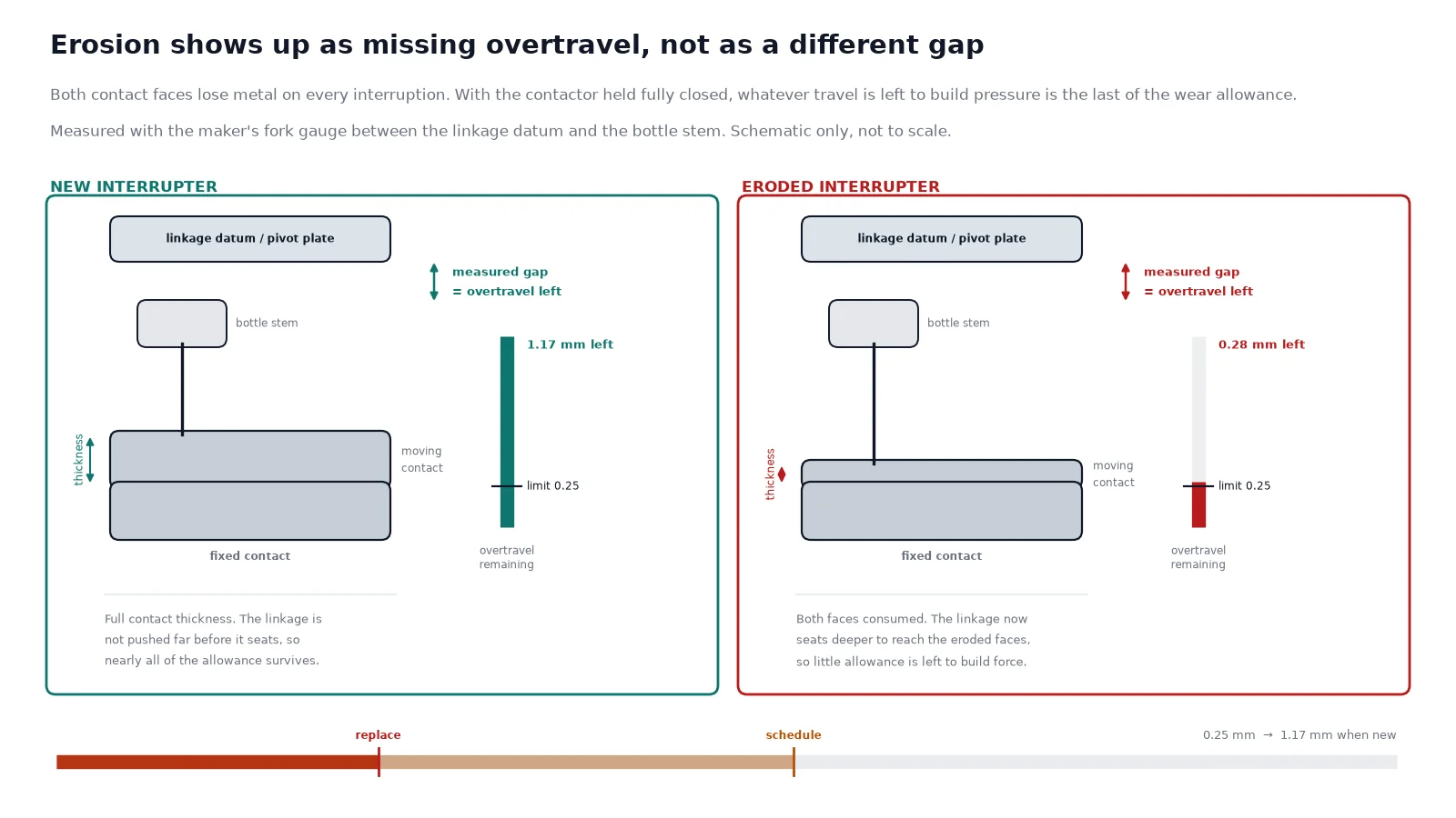
What happens physically is this. As the contact faces erode, the stack of metal between the fixed and moving contact gets thinner. The mechanism still closes to the same apparent position, because the actuator stroke does not change — so the travel that used to build contact pressure after first touch is progressively used up closing the gap. That excess travel is called overtravel, or wipe. It is the closest thing to a fuel gauge the design offers, and it is a direct readout of how much contact is gone.
The Three Limits Racing Each Other
Three numbers limit a contactor simultaneously, and most wrong decisions come from watching only one of them.
| Limit |
What it counts |
How it is expressed |
How you know where you are |
| Rated electrical life |
Load-breaking operations by utilisation category |
Published operation count for AC-3 and AC-4 |
Operation counter, corrected for duty mix |
| Mechanical life |
No-load operations before the mechanism wears out |
Published operation count, usually well above electrical life |
Mechanical counter, operating-time trend |
| Wear limit |
Permitted erosion or minimum overtravel for the model |
Millimetres, or a specific overtravel gap |
Direct measurement with a gauge |
The first two are budgets: you spend them at a rate you can only estimate. The third is a state: it tells you what is actually left. When the counter and the measurement disagree, trust the measurement. Two identical units with identical counts can sit at very different points of wear, because breaking current, power factor and jogging duty each change how much metal leaves the contact faces per operation — and because counters get replaced, get started mid-life, or register closing operations only.
Contact Overtravel: The Closest Reading of What Is Left
Overtravel is the only wear measurement that is both direct and accessible without opening the interrupter. The reference datum differs between constructions — some designs measure a gap between a pivot plate and the bottle stem, others between a crossbar and a bottle nut — so the procedure and the limit belong to the model, not the product family. Use the manufacturer’s gauge and the manufacturer’s number.
Published values show how wide the spread is. On one NEMA Size 4 vacuum contactor the new overtravel gap is about 0.046 in (1.17 mm) and the unit is replaced when any pole falls below 0.010 in (0.25 mm). On a 320 A frame from the same family, new is about 0.045 in and the replacement threshold is 0.020 in (0.51 mm). Same principle, different numbers, roughly a 1 mm band of usable wear. On medium-voltage contactors the equivalent published figures are a 5.5 ± 0.5 mm contact gap with defined overtravel on a 12 kV frame, and a 2.0 mm gap with 1.0 mm overtravel on a 1.14 kV frame.
How to Measure It
- Isolate and lock out all power circuits, including control power. Energising the coil is the easiest way to hold the contactor closed for measurement, and it is also the easiest way to get hurt — use a separate, correctly rated supply and treat the coil circuit as live.
- Close the contactor fully and hold it closed.
- Insert the manufacturer’s fork gauge between the datum surfaces on each pole, one pole at a time.
- Record the gap per pole. The lowest pole governs the verdict, not the average.
- Record the reading against the commissioning baseline and against the operation counter, in the same log entry.
One rule matters more than the rest: do not re-adjust the interrupter to restore overtravel. Once in service, overtravel is checked and not adjusted. Resetting it gives the mechanism more travel, removes the wear indication permanently, and does nothing about the thin contacts inside. The wear allowance exists precisely so the unit can be run until it is used up, and then be replaced as an assembly.
What the Numbers Look Like in Practice
Take a unit with a 0.046 in new gap and a 0.010 in replacement threshold. That is 0.036 in, or about 0.9 mm, of total usable erosion across both contact faces. Half of it is consumed when the reading reaches roughly 0.028 in. A contactor sitting at 0.022 in has around a third of its wear allowance left and should be scheduled, not watched. A contactor at 0.014 in is one busbar joint away from a temperature problem and should be on a short replacement list.
Contact Resistance: The Second Reading
Overtravel tells you how much metal is left. Loop resistance tells you what the remaining metal is doing electrically. Fresh copper-chromium contacts typically read in the range of 15 to 30 micro-ohms per pole; a rise of roughly 50 percent above the commissioning baseline is the usual flag for investigation. The measurement needs a four-wire micro-ohmmeter injecting 100 to 200 A DC, with parallel paths removed by opening disconnectors. An insulation tester cannot substitute for this — it measures a quantity several orders of magnitude away.
Resistance and overtravel answer different questions and can disagree. Eroded contacts with a stable resistance curve are a wear story, and the overtravel reading governs. A resistivity rise on one pole with normal overtravel is a contact-surface or joint story — pitting, oxide, a loose connection — and it is worth investigating before the wear calculation is even relevant. Comparing the three poles against each other catches alignment problems that a single-pole reading hides.
Vacuum Integrity: The Failure That Does Not Appear in the Counter
Field data on industrial contactor populations attributes roughly one failure in eight to loss of vacuum rather than to wear, and it is the failure that operation counting will never predict. A bottle can pass a dielectric test at borderline pressure and still fail to interrupt a fault, because arc extinction depends critically on vacuum quality rather than on the withstand figure alone.
The practical field test is an AC withstand across the open contacts at the same position the contactor occupies in service. A common reference figure for a low-voltage vacuum bottle is 5.5 kV at 50 or 60 Hz for one minute across a normal new gap without breakdown. Above about 5 kV across an open gap there is a possibility of X-ray generation, so test time should be kept short and personnel kept well clear. A bottle that flashes over, or that shows a leakage current climbing into the milliamp range, is finished.
Two supporting checks are worth adding. A magnetron discharge test is the more sensitive method for internal pressure, and it is the one to use on critical drives. A simple trend of withstand results at each major service is the cheaper substitute: a falling withstand voltage on one pole is a stronger warning than any single absolute reading, because vacuum loss is progressive.
Turning Operations Into a Maintenance Interval
A contactor’s counter is not one budget, it is two. The same physical operation costs very different amounts of contact metal depending on what the contactor was doing when it opened.
| Frame example |
Voltage class |
Electrical life AC-3 |
Electrical life AC-4 |
Ratio |
| 12 kV medium-voltage frame |
12 kV |
250,000 |
100,000 |
2.5 : 1 |
| 7.2 kV medium-voltage frame |
7.2 kV |
250,000 |
100,000 |
2.5 : 1 |
| Low-voltage frame, 1.14 kV |
1.14 kV |
600,000 |
60,000 |
10 : 1 |
The Duty Mix Is the Whole Calculation
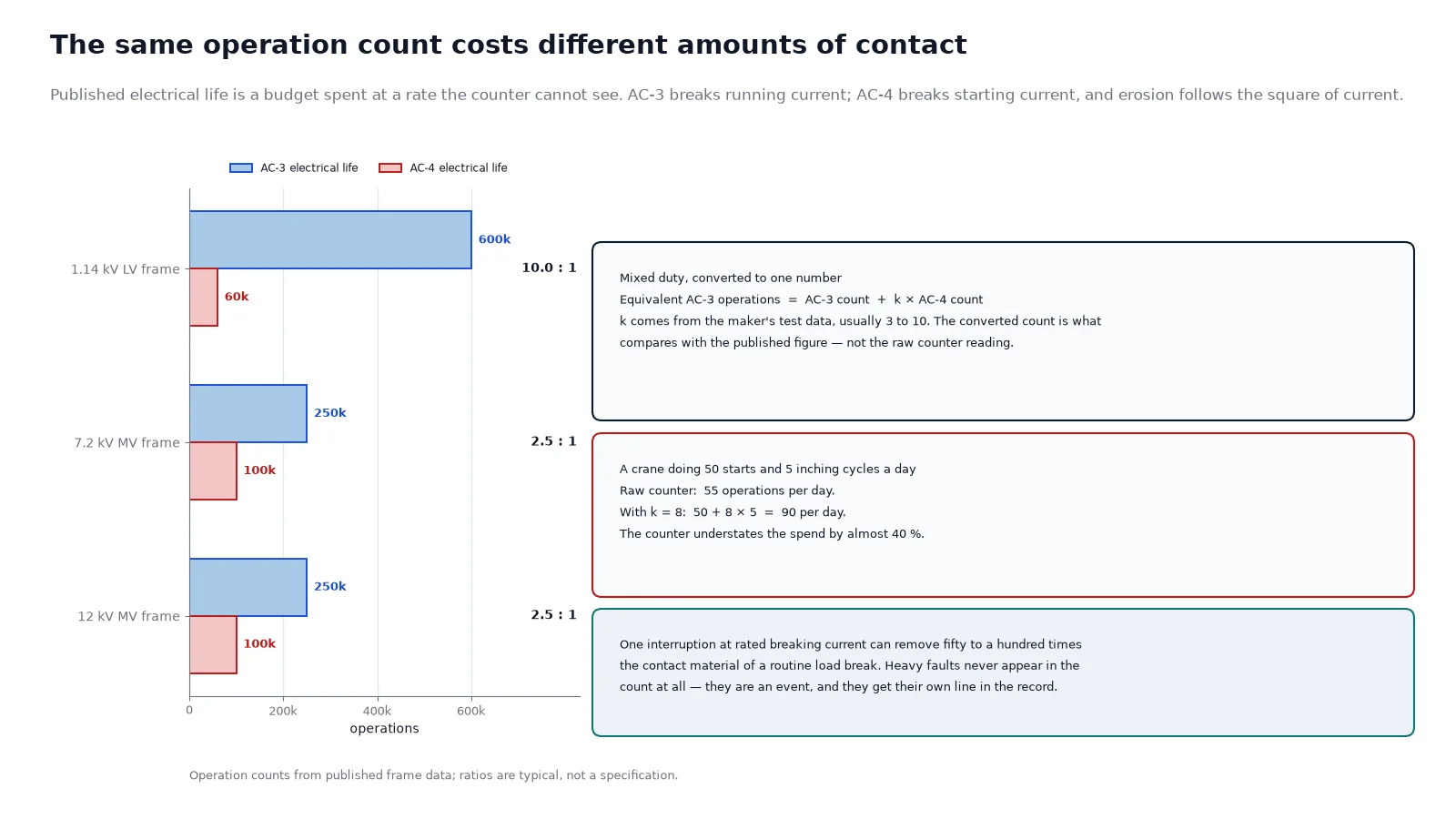
AC-3 is a motor that reaches speed before the contactor opens: the contactor closes onto starting current and breaks running current. AC-4 is a motor stopped before it reaches speed, or reversed, or inched: the contactor both makes and breaks the starting current. The arc energy at break is several times larger, and contact erosion is not linear in current — it behaves closer to the square. That is why the low-voltage frames show a 10 : 1 ratio while the medium-voltage frames show 2.5 : 1, and why “the catalogue says 250,000 operations” is not a maintenance interval.
Mixed duty is handled by converting to an equivalent count. Operations of each type are weighted so the total can be compared with one published figure — a weighting factor in the range of 3 to 10 applied to the AC-4 operations is the conventional approach, with the exact factor coming from the manufacturer’s test data. A crane drive doing 50 normal starts and 5 inching cycles a day is spending closer to 90 equivalent operations a day than 55. Cranes, hoists and reversing mill drives are the classic AC-4 population, and their contact life is spent several times faster than the schedule suggests when the duty mix is ignored. Vacuum contactors on rolling mill and heavy plant duty belong in this category by design.
Two further duty conditions shorten the interval. Capacitor switching exposes the contacts to high-frequency inrush and back-to-back restrikes that erode contact faces far faster than motor current does — the capacitor switching duty has its own selection rules. And frequent short interruptions, even at low current, accumulate arc time faster than the operation count implies.
What a Field Service Should Actually Cover
- Overtravel on every pole, measured with the correct gauge, compared with baseline and with the previous reading — not just against the absolute limit.
- Loop resistance on every pole at 100 to 200 A DC, with parallel paths removed.
- Withstand across open contacts, in the operating position, on a documented interval.
- Operation counter and duty mix recorded, with the equivalent operation figure calculated, not just the raw count.
- Mechanical timing and stroke, to catch mechanism wear before it shows up as pole discrepancy.
- Coil current and pick-up/drop-out voltage, since a coil drifting out of range is the first sign of a supply or coil problem. On latched designs this check belongs to a different part of the circuit entirely — the latch and hold comparison covers why.
- Terminal torque and thermal scan at main and control connections.
- Environment: condensation, dust, corrosion at the ceramic envelope. External contamination produces flashovers that imitate internal failure.
Interval follows the readings, not the calendar. Annual overtravel and resistance checks suit a climate-controlled switchroom. Move to six-monthly for dust-laden plants, coastal installations with salt exposure, or locations with machinery vibration transmitted into the cubicle. Bring the unit forward for any fault interruption at or near rating — a single heavy clearing event can remove fifty to a hundred times the material of a routine load break.
Keep Running, Watch, or Replace
| Condition |
Overtravel |
Loop resistance |
Withstand |
Action |
| Normal service |
Above 60% of allowance remaining |
Within 20% of baseline |
Passes |
Continue, annual check |
| Watching |
30 to 60% remaining |
20 to 40% above baseline |
Passes |
Shorten interval, plan replacement |
| Schedule |
Under 30% remaining |
40 to 50% above baseline |
Passes |
Replace at next planned outage, hold spare |
| Replace now |
Below the model minimum |
Over 50% above baseline on one pole |
Fails or leakage rising |
Remove from service |
Convergence is the trigger. When overtravel is close to the limit, resistance is drifting up, and the count is near the equivalent electrical life, the assembly comes out — the cost of a planned replacement is small against the cost of an unplanned outage or an arc flash event. Spare interrupters should be held on site for critical drives, because lead times for replacement assemblies routinely run into weeks.
Mistakes That Cost Contactors
- Judging wear by looking. The interrupter is sealed; appearance does not report erosion.
- Resetting overtravel. It restores the mechanism’s travel and destroys the only wear indication you have.
- Trusting the counter alone. A count without a duty mix is a budget figure, not a condition report.
- Measuring only one pole. Pole-to-pole spread is the earliest sign of misalignment, and the worst pole sets the limit.
- Using an insulation tester for loop resistance. Different quantity, different instrument, meaningless result.
- Ignoring a single heavy fault. One high-current interruption can be worth fifty routine ones.
- Skipping the withstand test because the contactor still switches. Units with a degraded bottle often perform perfectly until the fault they were installed to clear arrives.
The structural side of the device is worth knowing before the numbers mean anything: a contactor closes with an electromagnet, holds with a spring or a latch, and interrupts inside a sealed bottle. If any of that is unfamiliar, the vacuum contactor construction guide covers the assembly, and the comparison with a circuit breaker explains why the contactor is the device that carries the operation count in the first place. On older installations, the practical question is often whether to keep maintaining the existing frame at all — replacing an air contactor with a vacuum unit changes the maintenance story completely, because there are no contacts to dress and no arc chutes to clean.
The Takeaway
Contact wear in a vacuum contactor is measurable, not visible. Record overtravel and loop resistance at commissioning, measure on a schedule that matches the environment, convert the operation count through the actual duty mix, and treat the lowest pole as the verdict for the whole unit. When overtravel, resistance and equivalent operations converge on the limit, replace the interrupter assembly rather than adjusting it. The units that fail early are almost never the ones that looked bad — they are the ones nobody measured.
If you are specifying contactors for a duty cycle that will spend contact life quickly, or replacing units already at their wear limit, our medium-voltage contactor range lists published electrical life by utilisation category against each frame, and the ratings and electrical life guide walks through what those figures do and do not promise.
FAQ
How often should vacuum contactor contacts be inspected?
Annually in a clean, climate-controlled switchroom. Every six months in dusty, coastal or high-vibration installations. Immediately after any fault interruption at or near rated breaking current, regardless of the calendar. “Inspection” means measuring overtravel and loop resistance — the contacts themselves cannot be seen.
Can contact wear be assessed without dismantling the contactor?
Yes, and that is the normal method. Overtravel is measured with the contactor closed, using the manufacturer’s fork gauge between the datum surfaces. Loop resistance is measured with a four-wire micro-ohmmeter across the terminals of each pole. Neither requires opening the interrupter, which is not possible anyway.
What is a normal overtravel value for a vacuum contactor?
It depends on the frame. Published figures range from about 1.0 to 1.3 mm of new overtravel on small and low-voltage frames, with replacement thresholds between roughly 0.25 and 0.5 mm. Always use the value for the specific model: the datum and the limit are both model-specific, and a figure copied from another family will give a wrong verdict.
Should overtravel be adjusted back into range when it drops?
No. Once the contactor is in service, overtravel is checked and not adjusted. Adjusting it removes the wear indication and adds travel the contacts cannot absorb. The reduction in overtravel is the intended signal that contact thickness has been consumed, and the correct response is to plan replacement of the interrupter assembly.
Why do two identical contactors with the same operation count wear differently?
Because the count does not capture what each operation cost. Breaking current, power factor and jogging duty all change how much contact material leaves per interruption, and arc erosion scales closer to the square of current than linearly. One unit doing AC-3 motor duty and one doing crane inching can share a counter reading and be nowhere near the same condition.
How much contact material does one operation remove?
Under normal load switching, on the order of 0.1 to 0.5 mg per operation, which is why hundreds of thousands of operations fit in a millimetre or so of usable contact thickness. A single fault interruption at high current can remove fifty to a hundred times that amount, which is why heavy faults are tracked separately from the operation count.