Two vacuum contactors can carry the same 400 A, fit the same cubicle and cost within a few percent of each other, and still behave completely differently on the day the control supply dips. One stays closed and keeps the plant running; the other drops out and the process stops. The difference is not the interrupter — it is what holds the contacts closed.
There are two answers. A mechanically latched contactor is held closed by a latch that engages when the closing coil fires, and stays closed with no current in any coil until a trip coil releases it. An electromagnetically held contactor is held closed by the force of a holding coil that must be energised continuously. Everything else in this comparison — control wiring, protection requirements, coil life, energy consumption, failure mode — follows from that one sentence.
The Difference in One Sentence
The latched contactor remembers its state; the held contactor does not survive losing its supply. That is the whole decision, and it is a decision about which failure you can live with, not about which mechanism is better engineered.
| Behaviour |
Mechanical latch |
Electromagnetic hold |
| Holding force |
A mechanical latch, engaged at closing |
The holding coil, energised continuously |
| Coil current while closed |
Zero |
Continuous, typically a few watts per unit |
| Behaviour on loss of control power |
Stays closed. The load keeps running |
Opens immediately. The load stops |
| How it opens |
A trip pulse to the shunt-trip coil releases the latch |
De-energise the coil |
| Undervoltage protection |
Must be provided by a separate relay element |
Inherent in the mechanism |
| Control circuit |
Separate close and trip circuits, or a polarity-reversal coil |
Two-wire or three-wire with a seal-in contact |
| State indication |
Only from mechanically driven auxiliary contacts |
Auxiliary contacts mirror the coil state directly |
| Mechanical complexity |
Higher |
Lower |
| Typical cost |
Higher |
Lower |
Read the third row twice. It is the only row that changes the operating philosophy of a plant, and everything else is bookkeeping around it.
How Each Mechanism Latches, Physically
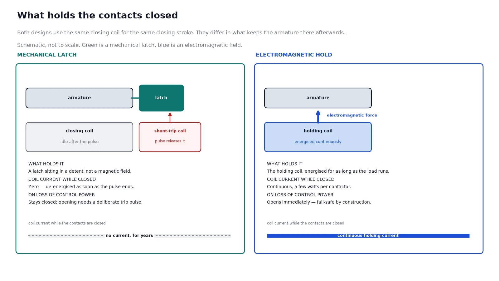
In the electrically held design, the closing coil is energised and its electromagnetic force pulls the armature through the closing stroke, compressing the opening springs. As long as that coil stays energised, the force holds the armature against the springs. Drop the supply, the force disappears, and the compressed opening spring drives the contacts apart. The mechanism is doing exactly what it should: a contactor with no control power is an open contactor.
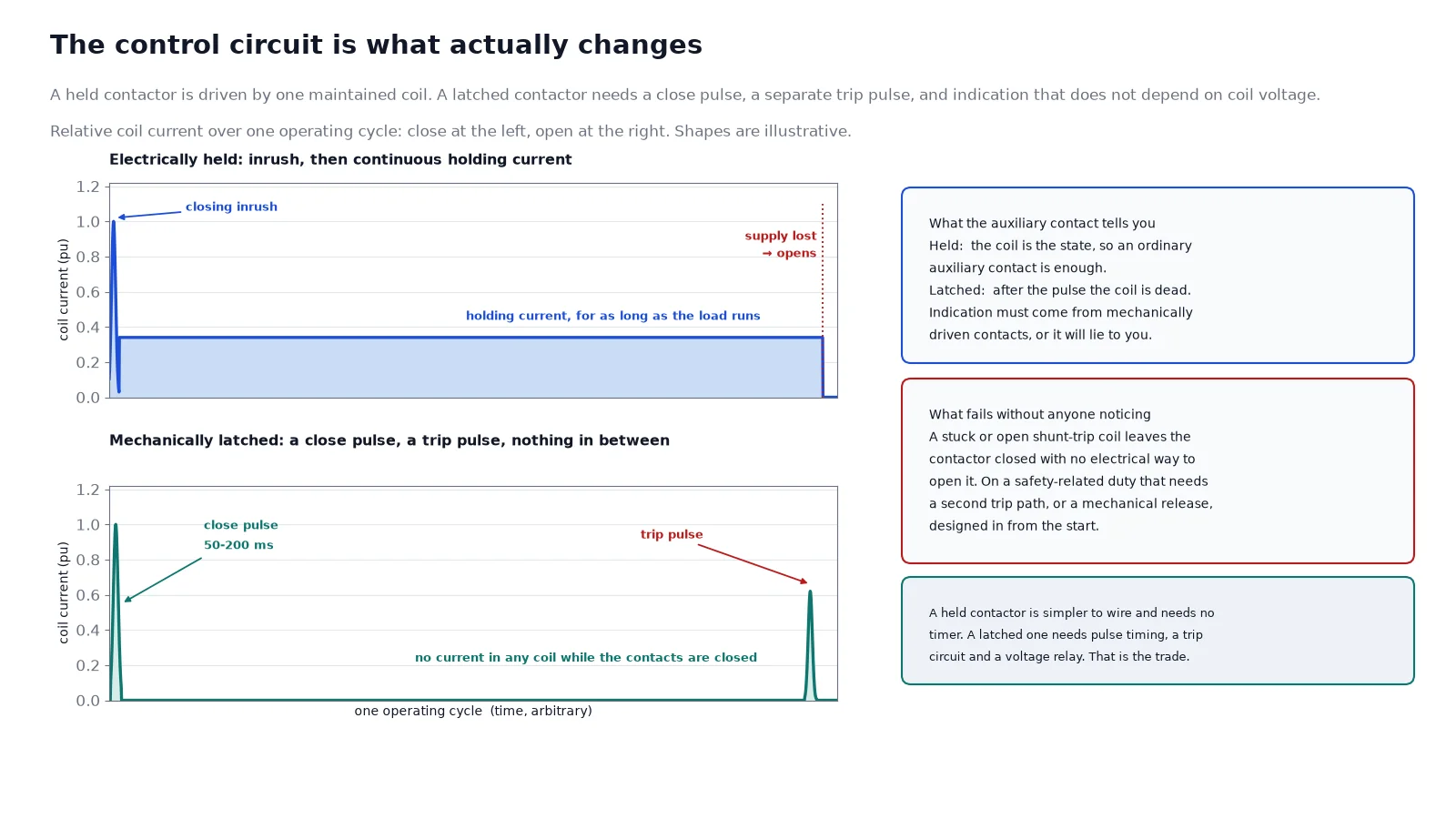
In the mechanically latched design, the same closing coil performs the same closing stroke, but at the end of the stroke a pawl or a bent plate drops into a detent on the drive arm and holds it there. The coil is then de-energised as soon as the closing pulse finishes, and the contacts stay closed because a steel latch is holding them, not a magnetic field. Opening requires a second coil. The shunt-trip coil pulls the latch clear of the detent, the stored energy in the opening spring is released, and the contacts part. Published opening times for a latched vacuum contactor sit in the 50 to 100 ms range after the trip coil is energised, which is fast enough for essentially every process requirement that is not itself a fault-clearing duty.
The closing and trip pulses are short. Fifty to two hundred milliseconds is normally sufficient, and the value should come from the manufacturer rather than from habit — too short and the latch does not fully engage, too long and the coil is heated for nothing. The single most common field failure in a latched installation is a closing pulse that was set marginally short on a cold morning, producing a contactor that appears to close, drops the latch on the first vibration, and is then diagnosed as a mechanical fault.
Which mechanism is in the box
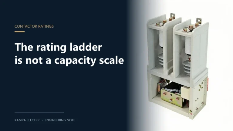
Chinese high-voltage contactors usually carry a suffix that distinguishes the holding method, with one letter for electrical hold and another for mechanical latch. That suffix is not always printed on the quotation, and the same series can be supplied in both configurations depending on the option list. The reliable field test is the coil schedule: a purely mechanical latch has no holding coil to draw current, so a datasheet that lists a closing coil, a holding coil and an optional shunt-trip coil is describing a design that can be ordered either way. The JCZ5 vacuum contactor publishes exactly that schedule — a closing coil, a holding coil and a shunt-trip coil — which is why the mechanism has to be confirmed per order rather than inferred from the family name.
What Loss of Control Power Actually Costs
Both behaviours are correct. The question is which one your process needs.
When staying closed is the right failure
On a remote pump station, an unattended substation or a capacitor bank on a pole, a contactor that drops out because the control supply sagged for 200 ms is a nuisance trip with a real cost: the pump restarts, the capacitor bank re-energises with its full inrush, and the whole restart sequence is repeated for a disturbance that had nothing to do with the load. Repeated energisation is not free. Capacitor energisation produces inrush currents of roughly 15 to 20 times rated, and transformer energisation 8 to 12 times rated for about 100 ms — every unnecessary operation is contact erosion that was paid for nothing. A latched contactor rides through the dip and the plant never notices.
The same logic applies to long duty cycles. A contactor holding a furnace or a heating load closed for hours gains nothing from a continuously energised coil; it only spends energy and thermally ages the coil insulation. A 60 W holding coil energised continuously for a year consumes around 526 kWh, and a panel with dozens of such contactors turns that into a line item. Pulse-only operation removes both the consumption and the thermal cycling.
When staying closed is a hazard
Anywhere an emergency stop or a safety circuit is expected to remove power from the load by de-energising the control circuit, a latched contactor defeats the design intent. The E-stop opens the control circuit, the latch holds, and the motor keeps running. This is not a subtle failure mode: it is a change to the safety architecture, and it has to be compensated with a separate, monitored undervoltage element that trips the contactor when control voltage is lost. That element needs its own settings, its own test and its own place in the cause-and-effect matrix.
Jogging and inching duty points the same way. Rapid start-stop cycles with a latched contactor mean a closing pulse and a trip pulse for every cycle, and the latch mechanism is a wear item in a way that a coil is not.
| Application |
Mechanical latch |
Electromagnetic hold |
Reason |
| Remote or unattended substation |
Preferred |
Risky |
No one is there to reset a nuisance trip |
| Capacitor bank switching |
Preferred |
Acceptable |
Avoids repeated inrush from control dips |
| Transformer primary switching, remote |
Preferred |
Acceptable |
Repeated energisation doubles stress on windings and bushings |
| Furnace and heating loads |
Preferred |
Acceptable |
Hours-long duty, no benefit from a live coil |
| Motor jogging and inching |
Poor fit |
Preferred |
Pulse delays fight the duty cycle |
| E-stop dependent safety circuit |
Needs added relay |
Preferred |
Fail-safe opening is inherent |
| Attended switchroom, stable supply |
Optional |
Preferred |
Simpler, cheaper, fail-safe |
Control Circuit Design Is Where Projects Slip
The two mechanisms do not share a control scheme, and a panel designed for one will not drive the other without changes.
An electrically held contactor suits a two-wire or three-wire control circuit: a maintained contact, or momentary pushbuttons with a seal-in auxiliary contact. The coil is the state, so the auxiliary contacts are enough for indication, and undervoltage protection comes free with the mechanism.
A latched contactor needs a separate close circuit and a separate trip circuit, or a single coil driven with reversed polarity. Three points have to be checked on the drawing before the panel is built.
- Pulse timing must be implemented, typically 50 to 200 ms, and it must be generated by a timer or an off-delay — a maintained close command will cook the closing coil.
- Status indication must come from mechanically driven auxiliary contacts. After the pulse ends the coil is dead, so coil voltage tells you nothing about whether the contacts are closed. Any indication wired to coil voltage is wrong.
- A backup trip path is required for safety-critical duties. If the shunt-trip coil fails open, the contactor stays closed indefinitely with no way to open it electrically. A second trip path or a mechanical means of release is not optional in that case.
The coil supply itself catches people too. High-voltage contactor closing and holding coils are frequently DC even when the control circuit is AC 110 V or 220 V, so the panel needs a rectifier module or a DC control bus. Wiring detail for both cases is in vacuum contactor coil voltage and wiring.
Voltage Dip: Deciding How Much Ride-Through You Need
The choice between the two mechanisms is usually made on a hunch about power quality. It is better made on data. Thirty days of power quality recording at the control supply point will show how often the voltage sags below about 85 percent of nominal and for how long, which is exactly the information needed to answer whether a held contactor would have dropped out in the last quarter.
Two qualifications keep that data honest. A short sag that ends before the contactor’s release time has no effect on either device, so the duration matters as much as the depth. And the recorded events must be counted against the actual restart cost — on a critical continuous process, one nuisance trip a year can justify the latched design outright, while on a non-critical load it will never pay for the added relay and the extra trip circuit.
A UPS-backed control supply is the third option, and it is a legitimate one: if the objective is only to ride through control dips while keeping fail-safe opening, a small UPS on the control bus achieves it with a held contactor and no change to the safety architecture. It is more to maintain than a latch and less to document.
Specification Checklist
Whichever mechanism is chosen, the same fields have to be stated. Values below are those published for the JCZ5 at 7.2 kV: 250 A, 400 A and 630 A frames; rated making capacity 2 500 A, 4 000 A and 6 300 A; rated maximum breaking current 2 000 A, 3 200 A and 5 040 A; 4 s short-time thermal current equal to the making capacity; 42 kV power-frequency withstand; 300 operations per hour; electrical life of 250 000 operations on AC-3 and 100 000 on AC-4.
| Field |
What to state |
| Holding method |
Mechanical latch or electrical hold, in writing, on the order |
| Control voltage |
AC or DC, and the value, separately for closing, holding and trip coils |
| Coil currents |
Closing, holding and trip current draw, to size the rectifier and the fuse |
| Pulse timing |
Required close and trip pulse length, from the manufacturer |
| Auxiliary contacts |
Number and type required, mechanically driven for latched units |
| Duty category |
AC-3 for motors brought to full speed, AC-4 for plugging, inching and reversing |
| Operations per hour |
The application’s real cycle, checked against the published limit |
| Short-circuit protection |
The fuse or upstream breaker that clears faults the contactor cannot |
The last row is the one that gets forgotten when the conversation is about holding mechanisms. A contactor switches; it does not clear fault current. Whether it is latched or held, the breaking rating is a coordination-level figure, and the high-current bolted fault is the fuse’s job. The relationship between the contactor and the fuse, and the difference between it and a breaker, is covered in CKG3, CKJ5 and JCZ5 selection and in what a vacuum contactor is.
Frequently Asked Questions
Can a mechanically latched contactor be converted to electrical hold?
No. The holding mechanism is part of the magnetic circuit and the mechanical assembly, not an add-on module. Changing the holding method means changing the contactor.
Does a latched contactor need a shunt trip to open?
Yes. With no current in any coil, there is nothing to release the latch. Without a trip pulse the contactor stays closed, which is also why a failed trip coil is a contactor that cannot be opened electrically.
Why does a latched contactor need an undervoltage relay?
Because it will not open when the control supply is lost. If the plant needs the load removed on undervoltage — for motor protection, for a safety circuit, or to prevent a re-energisation surprise — that function has to come from a separate voltage relay with its own settings and delay.
Which is better for a capacitor bank?
Mechanical latch, in most cases. Capacitor energisation produces inrush of roughly 15 to 20 times rated current, so every unnecessary reclose from a control dip is real contact erosion. A latched unit removes that source of repeated switching. The duty-side selection criteria are in vacuum contactor capacitor switching.
Does the holding coil really consume enough energy to matter?
Not on one contactor. A holding coil of a few watts is nothing. Across a panel with dozens of contactors holding for thousands of hours a year it becomes both a measurable energy line and a continuous thermal load on coil insulation, which is where the argument for latch actually lands.
What happens to electrical life on a latched contactor used for jogging?
It is spent faster than the datasheet suggests, because every jog is a close and a trip pulse, and the AC-4 figure applies to opening on starting current. The published counts, and how they convert into years, are set out in vacuum contactor ratings and electrical life.
The Short Version
Choose the latch when an unwanted opening costs more than an unwanted closure: remote sites, capacitor banks, transformer primaries, long-duty heating. Choose the hold when a failure to open is the more serious risk: safety circuits, jogging duty, attended switchrooms with clean control power. Then state the choice explicitly on the order, because the coil schedule on the datasheet is the only thing that will tell you which mechanism actually arrived — and design the control circuit for the mechanism you chose, not for the one the last project used.