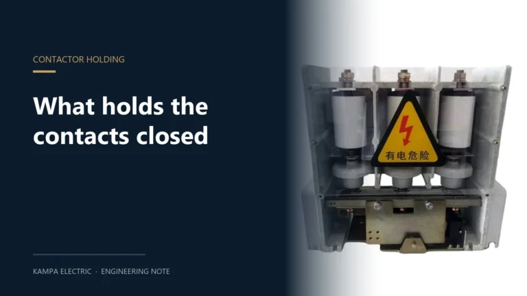
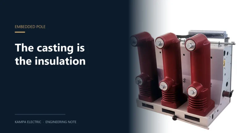
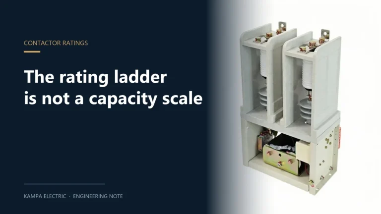
Three devices hang on the same overhead feeder and buyers routinely treat them as one purchase. They are not. An auto recloser interrupts fault current and closes itself again; a sectionalizer cannot interrupt fault current at all and only opens while the line is already dead; a vacuum circuit breaker interrupts fault current and then waits for a human or a SCADA command. Get that hierarchy wrong and the coordination study will not close, no matter how good the equipment is.
This article separates the three by what each one is physically able to do, then works through the settings that make them cooperate: reclose sequences, dead times, counting rules and lockout. Ratings used as examples are those of the ZW32M pole-mounted vacuum circuit breaker, which is the same frame whether it is ordered as a breaker or as a recloser — the controller is what changes.
The One Question That Decides Everything
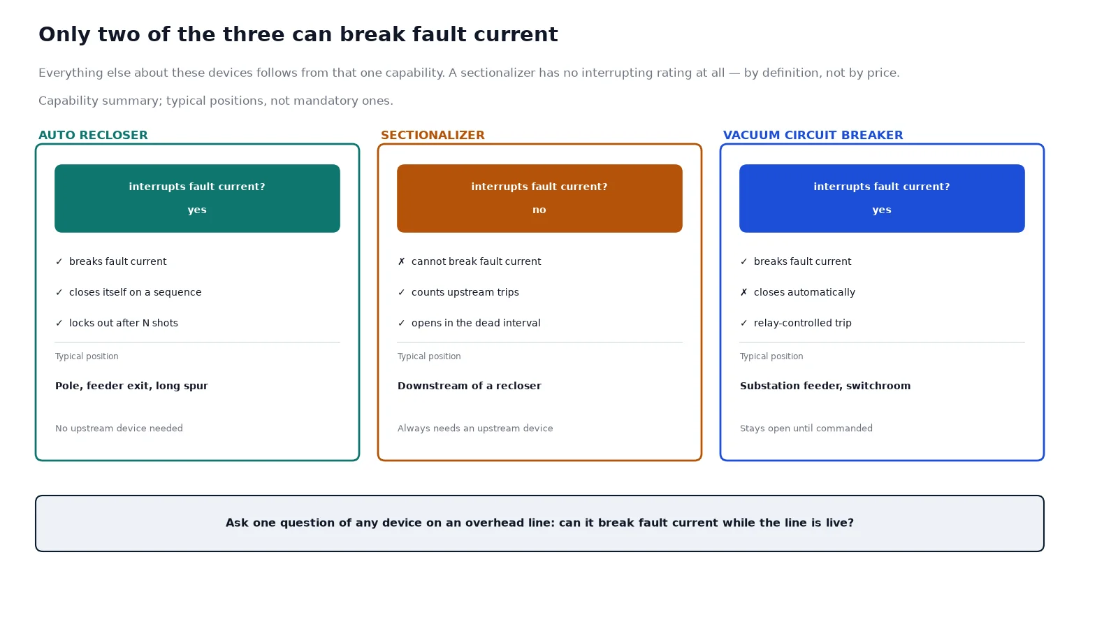
Ask a single question of any device on an overhead line: can it break fault current while the line is live? The answer sorts the three devices completely, and every other difference follows from it.
| Capability |
Auto recloser |
Sectionalizer |
Vacuum circuit breaker |
| Breaks fault current |
Yes, at its rated interrupting current |
No, not at any fault level |
Yes, at its rated interrupting current |
| Detects the fault itself |
Yes, integrated relay and controller |
Counts current pulses; does not decide on fault magnitude |
Only through an external protection relay |
| Closes automatically |
Yes, on a programmed sequence |
Closes on line voltage restoration |
No. Manual or SCADA command only |
| Opening condition |
Fault current |
Dead line, after N counted operations |
Relay trip command |
| Typical location |
Pole, feeder exit, long spur |
Downstream of a recloser, mid-feeder |
Substation feeder, switchroom |
| Needs an upstream device |
No |
Yes, always |
For reclosing, yes |
That table is the whole comparison in six rows. Everything below explains why each row reads the way it does, and where the money goes.
What an Auto Recloser Actually Does
Most faults on an overhead line are not permanent. A branch touches a conductor, a bird bridges a gap, an insulator flashes over in a lightning strike, salt spray tracks across a surface. The arc extinguishes in a fraction of a second once the current stops, and the line is healthy again — but only after someone drives out and closes the breaker, unless the device can close itself.
An auto recloser is a circuit breaker with the protection relay and the reclose logic built into the same housing. It measures current, decides that a fault exists, opens, waits a defined dead time, and closes. If the fault is still there, it opens again and repeats, up to a programmed number of attempts, then locks out. The commonly quoted figure is that 70 to 80 percent of overhead faults are transient. Treat that as an order-of-magnitude rule of thumb rather than a measured constant — the real ratio depends on vegetation, wildlife, pollution and lightning density, and on a heavily treed rural spur it can be higher while on a clean coastal industrial feeder it is lower.
The dead time is the engineering decision, and it is chosen for two different reasons at once. It has to be long enough for the fault arc to de-ionise and for the surrounding air to recover dielectric strength, which is why the first reclose is short — typically around half a second — and later ones are longer, commonly in the two to five second range. It also has to be long enough for downstream devices to complete their own operation, which is where coordination starts.
| Shot |
Typical dead time |
What it is for |
| First reclose (fast) |
0.3 to 0.6 s |
Clear a transient arc before any downstream device counts it |
| Second reclose (fast or first delayed) |
0.5 to 2 s |
Second attempt at a self-clearing fault |
| Delayed shots |
2 to 5 s, or longer |
Give downstream fuses and sectionalizers time to operate |
| Lockout |
After the final shot |
Hold open until a crew attends |
A sequence described as “2 fast, 2 delayed” means four trip operations and three reclose attempts. The number matters commercially, not just technically: each reclose into a persistent fault is another full fault-current interruption, and the interrupter’s life is spent in those operations. A device rated for a certain number of fault interruptions does not care whether the faults were transient.
Why a Sectionalizer Cannot Do the Same Job
A sectionalizer is a load-break switch with a counting function. It has no interrupting rating for fault current — that is not a limitation of a cheap model, it is the definition of the product. It opens only when the current through it is already near zero, which happens during the dead time after an upstream recloser or breaker has cleared the fault.
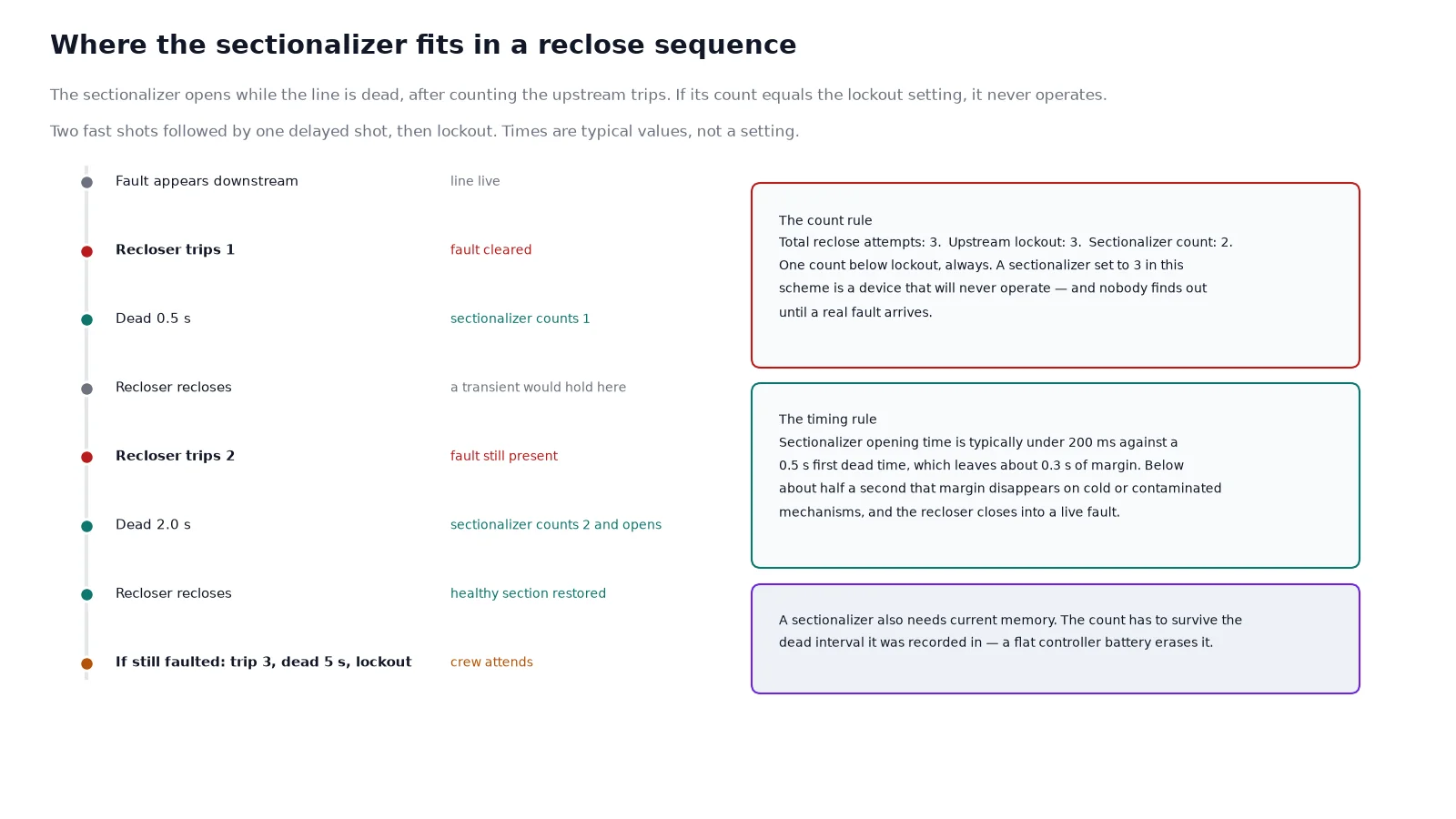
The sequence it lives inside looks like this. A fault appears downstream. The upstream recloser sees fault current and opens. The sectionalizer, which also saw that current, increments its count and remembers it. Line voltage disappears, and during that dead interval the sectionalizer opens its contacts with no current to break. The recloser then closes. If the fault was beyond the sectionalizer, the section is now isolated and the recloser holds — supply is restored to everything upstream of the open sectionalizer. If the fault was upstream of it, the recloser trips again and the count continues.
Three details decide whether this works in practice.
The count setting must be lower than the upstream lockout
If the recloser locks out on the third trip, a sectionalizer set to count three will never reach its count, because the line stays dead after lockout and there is no further operation to count. The working rule is one count below the upstream lockout setting: a three-shot recloser pairs with a sectionalizer set to two. A sectionalizer set to three in the same scheme is a device that will never operate, and nobody discovers it until a fault does.
The opening time has to beat the reclose
The sectionalizer must complete its mechanical opening inside the dead time. Published opening times are typically well under 200 ms, which leaves room inside a 0.5 s dead time, but the margin shrinks on cold, contaminated or poorly maintained mechanisms. This is the reason dead times below about half a second are avoided in humid climates: the contacts become sluggish, the sectionalizer is still moving when the recloser closes, and it closes into a live fault it cannot break.
It needs current memory, not just a current sensor
The counting logic has to survive the loss of supply between operations, because the whole point is to remember something that happened while the line was dead. Loss of that memory — a flat battery on a controller that was meant to be self-powered — turns the device into an expensive load-break switch. On a pole in a remote location the battery and its charger are as much of the specification as the interrupter.
Where a Plain VCB Is the Right Answer
Not every feeder wants automatic reclosing, and a device that recloses when it should not is worse than one that does not reclose at all. A vacuum circuit breaker under relay control gives the operator a deliberate decision at every step.
The case for a breaker is strongest at the feeder origin inside a substation, where the busbar, the switchgear and everything downstream are designed around a defined protection scheme, and where reclosing decisions belong to the network operator’s policy rather than to a pole-top controller. It is also the right answer wherever reclosing must be blocked: a feeder with embedded generation, a feeder supplying a large motor load that cannot tolerate a second voltage dip, or an industrial feeder where a reclose onto a fault would put a restart sequence through equipment that has just been through one.
The mechanical and electrical endurance figures are also different in character. A breaker in a substation is expected to spend most of its life carrying current and very little of it operating; its ratings are built around a rated short-circuit breaking sequence and a mechanical life in the thousands to tens of thousands of operations. A recloser on a rural spur may execute several operations per fault event across twenty years of transients. Both are vacuum interrupters, but the duty they are bought for is not the same, and the nameplate parameters are read differently as a result. On an outdoor frame the choice between the common 12 kV pole-mounted families is set out in VS1, ZW32 and ZW7 compared.
Fuse Saving and Fuse Blowing
On a feeder protected by both a recloser and downstream fuses, the sequence setting is a policy choice with two distinct outcomes.
Fuse saving uses a fast reclose that operates before any downstream fuse has had time to melt. A transient fault is cleared by the recloser, the fuse is untouched, and the customer never sees an outage long enough to notice. The cost is that a permanent fault downstream is now fed through several reclose attempts, and the fuse eventually operates on a delayed shot with more energy behind it.
Fuse blowing deliberately gives the fuse time to operate first. The fuse clears the faulted spur and the whole feeder never loses supply. The cost is that every transient fault on that spur also blows the fuse, and someone has to replace it.
Which one a network uses is a utility policy decision, and it changes the numbers a supplier must be told: the fast curve has to be faster than the minimum melting time of the smallest downstream fuse, and the delayed curve has to sit above the total clearing time of the largest. A recloser specified without the downstream fuse sizes is a recloser whose curves cannot be set.
Specifying an Auto Recloser: The Fields That Matter
Most quotation errors are omissions rather than wrong values. The ZW32M frame illustrates the format: it is built at 12 kV or 24 kV as separate constructions, 630 A or 1 250 A continuous, 20 kA or 25 kA short-circuit breaking, 42 kV power-frequency withstand at 12 kV class and 65 kV at 24 kV class, with lightning impulse withstand of 75 kV and 125 kV respectively, and a permanent magnet actuator with capacitor energy storage.
| Field |
What to state |
Why it is missed |
| System voltage and class |
Nominal voltage plus the equipment class, for example 11 kV on a 12 kV frame |
Buyers quote nominal only, and a 24 kV requirement is then discovered late |
| Continuous current |
Load current, not transformer rating |
Derated by ambient and enclosure, not by the datasheet headline |
| Interrupting current |
Prospective fault level at the point of installation |
Substation fault level is used, which overstates the pole position |
| BIL |
Lightning impulse withstand required by local practice |
Assumed rather than stated, then mismatched with the line insulation |
| Reclose sequence |
Number of fast and delayed shots, each dead time, lockout behaviour |
Left at factory default, which rarely matches the network |
| Protection functions |
50/51, 50N/51N, 79, 27/59 and faulted phase indication |
Assumed to be included; sometimes only the reclose element is |
| Communications |
DNP3, IEC 61850 or Modbus, and the point list |
Protocol named, point list never agreed, integration fails at commissioning |
| Auxiliary supply |
AC or DC, voltage, and battery autonomy for the controller |
Battery and charger treated as accessories rather than part of the unit |
| Actuator |
Permanent magnet or spring, and the stored-energy source |
Determines operating time and what happens on loss of control power |
| Single-phase tripping |
Whether independent pole operation is required |
Only raised after the quotation, and changes the frame |
The actuator row deserves a note of its own, because it decides behaviour on a bad day. A permanent magnet actuator holds the closed position with magnetic force and stores the energy to open in capacitors, so a control supply failure does not by itself open the breaker — which is either exactly what you want or exactly what you must not have, depending on policy. A spring mechanism makes the same decision differently. The comparison is set out in permanent magnet versus spring mechanism.
The Coordination Study Is the Deliverable
Devices that are individually correct still fail as a scheme. Three checks catch most of it before the equipment is ordered.
The first is grading with the upstream protection: the recloser’s curve has to sit below the substation breaker’s curve at every fault level, including the minimum fault current at the end of the feeder, not just the maximum at the origin. The second is the sectionalizer count rule described above. The third is the earth-fault path, which is where overhead schemes most often go wrong — an earth fault at the far end of a long feeder produces a current that is small compared with the phase fault level, and a setting chosen from the phase study alone will not see it. The wider method is covered in transformer and feeder protection coordination.
Surge protection belongs in the same conversation for a different reason. A recloser that closes back into a line still carrying a lightning-induced surge, or a feeder whose arresters are graded for the wrong earthing method, will produce failures that look like device failures and are not. The selection logic is in 10 kV surge arrester selection.
One more choice belongs at this stage rather than later: the interrupting medium inside the device. Vacuum and SF6 behave differently on capacitor and reactance switching, and the choice now affects what the controller has to be told about restrikes and gas monitoring. The trade-offs are in SF6 versus vacuum switchgear.
Common Specification Errors
- Buying a sectionalizer for a position that needs interrupting duty. If no upstream device can clear the fault, a sectionalizer will simply sit there while the fault burns.
- Setting the count equal to the lockout. The device never operates and the error is invisible until the first permanent fault.
- Quoting nominal voltage only. A 24 kV requirement and a 12 kV frame are different products, not a configuration option.
- Assuming “remote control” means reclosing. Remote operation, monitoring and automatic reclosing are three separate purchases with three separate hardware sets and three separate commissioning tests.
- Leaving the sequence at factory default. The default is a starting point, not a coordination setting.
- Specifying the protocol without the point list. The protocol determines whether the master station can talk; the point list determines whether there is anything to say.
Frequently Asked Questions
Can a sectionalizer be used without a recloser?
Not usefully. It has no fault-interrupting capability, so something upstream must clear the fault and create the dead interval during which it opens. That upstream device can be a recloser or a circuit breaker with a reclose function, but it cannot be another sectionalizer.
What is the difference between an auto recloser and a circuit breaker?
Both interrupt fault current. The recloser closes itself again on a programmed sequence; the breaker stays open until a person or a SCADA command closes it. In practice a recloser is a breaker with the protection relay and the reclose logic integrated into a pole-mounted unit, which is why it can operate unattended.
How many reclose attempts should a feeder have?
Two fast attempts followed by one or two delayed attempts is the common pattern, and three to four total attempts is typical. The real answer comes from the coordination study: the number of attempts must be consistent with the sectionalizer count settings and with what the downstream fuses and the load can tolerate.
Why is the first dead time shorter than the later ones?
Because the first reclose is aimed at a transient fault, and a transient only needs long enough for the arc to de-ionise — around half a second. Later shots are aimed at giving downstream protection time to operate and isolate a permanent fault, which takes seconds rather than milliseconds.
Should reclosing be blocked on a feeder with distributed generation?
As a rule, yes, unless the scheme has been studied for it. An uncontrolled reclose can close out of phase with an embedded generator, and the resulting torque and current stress is not something either the generator or the recloser is rated for. Where reclosing is retained, it is usually with a voltage check or a synchronism check.
Can a pole-mounted VCB be converted to a recloser later?
On the same frame, often yes: the interrupter and the pole assembly are the same, and the reclosing function lives in the controller. Whether a specific unit can be upgraded depends on whether the secondary wiring, the current sensors and the controller interface were provisioned at build. This is worth deciding at order stage rather than after installation, because retrofitting sensors into an energised pole-mounted unit is a scheduled outage.
The Short Version
If the position must clear faults, it needs interrupting capability — a recloser or a breaker. If the position only needs to isolate a section that something else has already de-energised, a sectionalizer does that job at a fraction of the cost and with no interrupting duty to maintain. The recloser is what makes an overhead feeder self-healing; the sectionalizer is what keeps that self-healing from restoring supply into a faulted section; the breaker at the origin is what defines the fault level both of them coordinate against. Order them as a scheme, with the sequence, the counts and the curves stated in the same document, or expect to redo the study at commissioning.