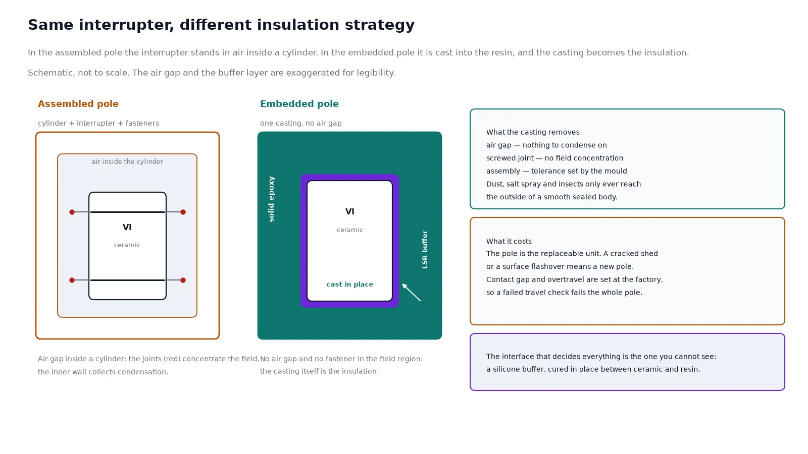
An embedded pole vacuum circuit breaker looks, from the front, almost identical to an assembled one: same spring mechanism, same front plate, same three poles rising out of the truck. The difference is inside the red casting. In an assembled pole the vacuum interrupter sits in an air space inside an epoxy cylinder, clamped by screws and sealed at the ends. In an embedded pole the interrupter, the conductors and the terminals are cast into a single solid block of epoxy, and that block becomes the insulation.
The consequence is that the pole’s reliability is decided at the casting machine, not at the assembly bench. This guide covers what APG casting actually is, why the buffer layer between ceramic and resin is the whole technology, and what an embedded pole does and does not fix once it is on site. The ratings referred to throughout are those of the VBI-12 indoor vacuum circuit breaker.
What an Embedded Pole Replaces
The traditional pole is an assembly. An epoxy or porcelain cylinder provides the external insulation, the vacuum interrupter is mounted inside it, and threaded fasteners hold the current path together. Each of those interfaces is a place where the electric field concentrates, and each is a place where air, dust and moisture can collect over twenty years of service.
| Item |
Assembled pole |
Embedded pole |
| Insulation medium |
Air space inside a cylinder |
Solid epoxy, no air gap |
| Current path |
Screwed or bolted joints |
Cast through, no fasteners in the field region |
| Field distribution |
Concentrated at fasteners and electrode edges |
Graded by the casting geometry and the screen |
| External contamination |
Dust and moisture settle on inner surfaces |
Sealed body; surface is smooth and cleanable |
| Assembly tolerance |
Set by the fitter |
Set by the mould |
| Replacement |
Interrupter or cylinder can be changed |
Whole pole is replaced as one part |
The first four rows explain why the design exists. The last row is the price, and it is worth stating plainly at the start: an embedded pole cannot be repaired in the field, and a damaged casting is a replacement, not a repair.
The APG Cycle, Stage by Stage
Automatic pressure gelation is a specific process, not a marketing term for “cast in resin”. The resin system and the hardener are metered with a silica filler, mixed under vacuum, and injected under pressure into a mould that is already hot. The heat is what does the work: the resin gels in the mould rather than curing slowly in an oven, so the mould can be opened and reused within the hour.
| Stage |
APG (pressure gelation) |
Vacuum casting |
| Mixing and degassing |
Under vacuum below 500 Pa absolute, 1 to 2 hours at about 40 °C |
Under vacuum, about 1 to 2 hours at 60 °C |
| Filling |
Injected under 0.5 to 5 bar pressure |
Drawn into the mould inside a vacuum chamber |
| Mould temperature |
130 to 150 °C |
80 to 100 °C |
| Gel or cure in mould |
10 to 30 minutes |
3 to 6 hours |
| Post-cure |
130 to 140 °C for 6 to 10 hours |
130 to 140 °C for 6 to 10 hours |
The process was patented in 1969 and has been the standard route for medium-voltage cast insulation ever since. What matters for a buyer is the last three rows together. Because the resin gels in 10 to 30 minutes rather than curing for 3 to 6 hours, the mould turns over several times per shift, which is why APG became the economical way to cast complex solid parts — and why an under-cured part is a real risk at a factory that is pushing throughput. The post-cure is where that risk is resolved: without the full 6 to 10 hours, the glass transition temperature stays below specification and the part behaves like a different material in service.
Pressure is the other half of the story. Filling at 0.5 to 5 bar compresses any residual bubble to a fraction of its volume, and the hot mould wall keeps the resin viscosity low long enough for the fill to complete before gelation starts. The result is a part with no connected voids — which is exactly what a partial discharge measurement is looking for.
Why the Buffer Layer Is the Whole Technology
Cast the interrupter directly into epoxy and the pole cracks. Not immediately, and not on the bench — it cracks after a few hundred thermal cycles, when the aluminium-oxide ceramic housing of the interrupter and the filled epoxy around it expand by different amounts.
The numbers are not subtle. Alumina ceramic has a coefficient of thermal expansion around 7 to 8 × 10⁻⁶ per kelvin. A filled epoxy casting runs at roughly 25 to 40 × 10⁻⁶ per kelvin, depending on the filler loading. Over a 100 K swing, the ceramic moves about 0.8 mm per metre while the resin moves 3 mm per metre or more. Across a pole 100 mm in diameter, that is a difference of a quarter of a millimetre that the interface has to absorb without either cracking the ceramic or delaminating from it.
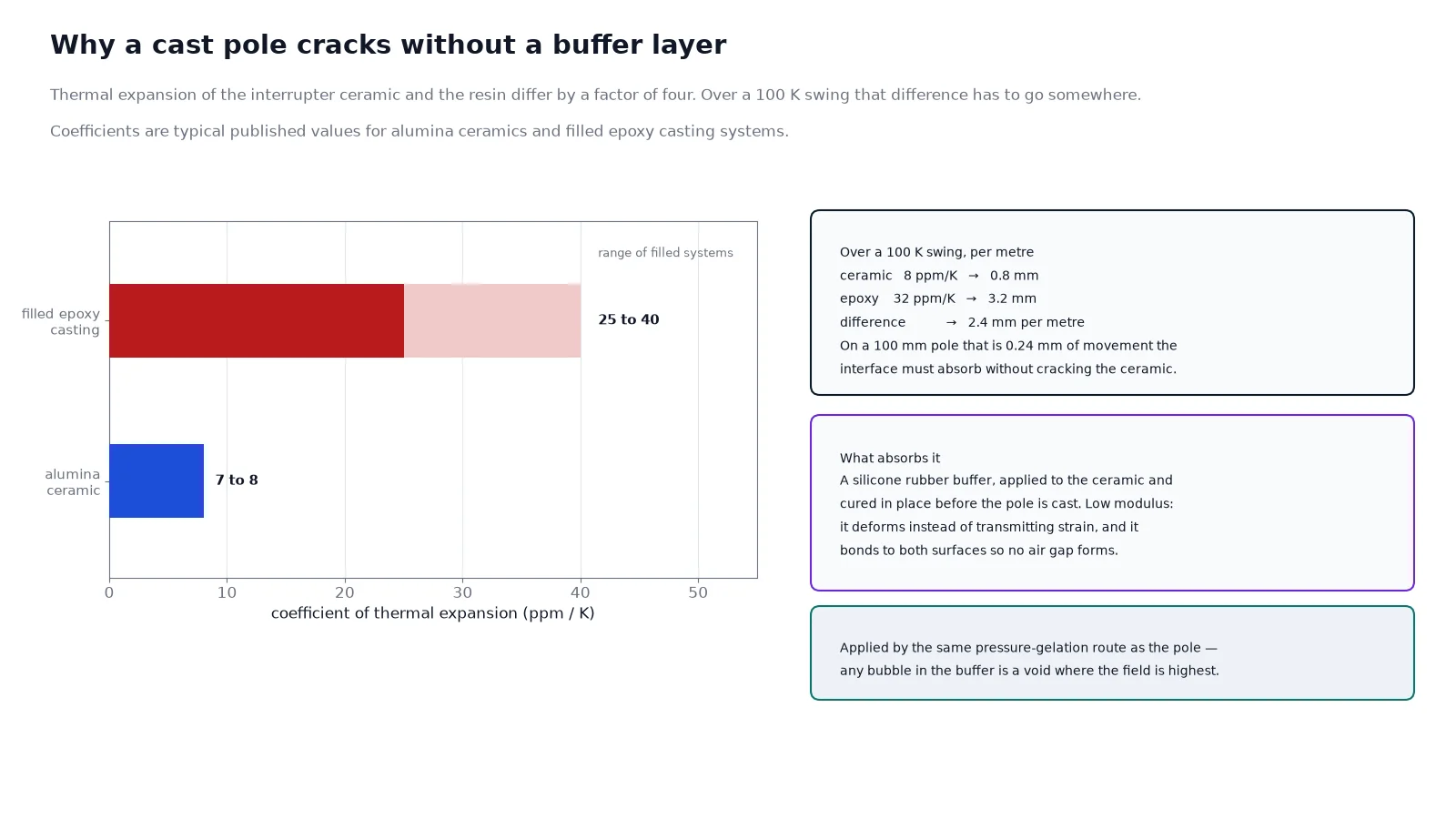
The answer is a compliant layer between the two. A liquid silicone rubber buffer is applied to the ceramic housing and cured in place, and the epoxy is cast over it. The silicone has a low modulus, so it deforms instead of transmitting the strain, and it bonds to both surfaces so no air gap forms. The layer has to be applied by the same pressure-gelation route, because any bubble or unbonded patch in the buffer becomes a void at the exact interface where the field is highest — which is why the process is often described as a double APG cycle, one for the buffer and one for the pole.
This is where the quality of two suppliers can differ while their datasheets look identical. The buffer layer is not visible in a finished pole, is not listed in a parameter table, and cannot be checked by a witness at final assembly. It shows up only in the thermal cycling test and in the partial discharge record.
Voids, Partial Discharge and the Humid Site
A void inside solid insulation is worse than a void in air. The dielectric constant of the gas in the cavity is lower than the resin around it, so the field in the cavity is higher than the field in the bulk. Above a threshold, the cavity breaks down, and the discharge erodes the resin wall a few molecules at a time. The pole does not fail that day. It fails years later, usually in the season when humidity is highest.
This is why partial discharge is the acceptance test that matters for an embedded pole, and why the number should be read at the pole level rather than at the breaker terminals. Suppliers of solid-insulation poles commonly publish a pole-level figure of 5 pC or below at 1.2 times the highest voltage for equipment; a pole that measures an order of magnitude above that has a casting problem, even if it passes the power-frequency withstand.
Humidity is the amplifier. An assembled pole breathes: the air inside the cylinder follows the ambient, and in a coastal or tropical installation it condenses on the inner surfaces during the cool part of the cycle. The condensation layer is not a dielectric failure by itself, but it distorts the field and it carries contamination into the gap. An embedded pole has no inner surface to condense on. The primary circuit is entirely inside the resin, so dust, salt spray, insects and condensation only ever reach the outside of a smooth, sealed body — the failure mode is removed rather than managed.
What the Pole Changes on Site
Maintenance. There is no insulation to clean and no interrupter to adjust. The maintenance scope reduces to the mechanism: lubrication, the auxiliary switch, the closing and opening coils, and the counter. For a switchgear fleet in a humid climate, that is the difference between an annual shutdown and a five-year one.
Footprint. Solid insulation replaces the air clearance that an assembled pole needs between the interrupter and the cylinder wall, so the pole is smaller for the same voltage. That translates into a shallower cubicle or a higher rated voltage in the same width — which is why the same 12 kV frame can be offered at 24 kV in an embedded design.
Altitude and pollution. Because the external insulation is a creepage path over a solid surface rather than an air gap, the altitude correction that applies to air clearance is less severe, and the creepage can be built into the shed profile. The usual ladder is about 20 mm per kV at pollution degree II, 25 mm per kV at degree III and 31 mm per kV at degree IV; a pole specified for a coastal site should be quoted with the creepage figure, not just the voltage.
Seismic and vibration. A cast body has no fasteners to work loose. In an application where the breaker sits on a structure that vibrates — a mill, a crusher house, a wind substation — the assembled pole’s screwed joints are the weak point and the embedded pole simply does not have them.
What It Does Not Fix
An embedded pole is a better insulation system. It is not a better breaker, and three limits are worth understanding before it is specified.
- The mechanism still sets the life. The VBI-12 is published at 10,000 mechanical operations, which corresponds to mechanical class M2 in the IEC 62271-100 classification. The pole will outlast the mechanism by a wide margin at normal switching rates, but at 10 operations an hour the mechanism is consumed in about three years of continuous duty, and the fact that the insulation is maintenance-free does not extend it.
- A pole is not field-repairable. A flashover across the external surface, a deep mechanical gouge, or a cracked shed means a new pole. On a five-year-old breaker that may be an obsolescence problem rather than a spares problem, so the pole part number is worth recording at commissioning.
- Thermal shock has a limit. The buffer layer absorbs the differential expansion, but it is not unlimited. Poles are type-tested over something like -40 °C to +125 °C cycling; a cold-climate site below the published ambient range needs the low-temperature variant, not just a reassurance that “it is cast solid”.
There is also a commissioning point that catches people out: the interrupter inside an embedded pole cannot be adjusted. Contact gap, overtravel and the opening damper are set at the factory and checked by the mechanical characteristics test, so a breaker that fails a travel measurement cannot be re-shimmed in the field the way an assembled pole can. The measurement is a pass or fail on the whole pole.
The VBI-12 Ratings
| Parameter |
Published value |
| Rated voltage |
12 kV |
| Rated current |
630 / 1,250 / 2,000 / 3,150 A |
| Short-circuit breaking current |
20 / 25 / 31.5 / 40 kA |
| Short-circuit making current, peak |
50 / 63 / 80 / 100 kA |
| Short-time withstand |
20 / 25 / 31.5 / 40 kA for 4 s |
| Power-frequency withstand |
42 kV for 1 minute |
| Lightning impulse withstand |
75 kV |
| Operating sequence |
O-0.3 s-CO-180 s-CO |
| Mechanical life |
10,000 operations |
| Capacitor bank breaking |
630 A single bank, 400 A back-to-back |
| Ambient temperature |
-10 °C to 40 °C, storage to -30 °C |
| Standards |
IEC 62271-100, GB 1984 |
Two rows deserve attention. The 42 kV power-frequency and 75 kV impulse withstand are the values for the 12 kV class, and they are what the creepage and the casting thickness are designed around — the pole does not gain insulation margin simply because it is solid. And the 10,000 mechanical operations are the practical ceiling on the whole device at high switching rates, as described above. The 630 A single-bank and 400 A back-to-back capacitor ratings are worth reading alongside the nameplate parameter guide, because the two figures describe two different duties on the same interrupter.
If the question is whether the load needs a breaker at all, the contactor against breaker comparison covers the boundary; the embedded pole sits firmly on the breaker side of it, where fault current has to be interrupted rather than merely switched.
Checking the Casting Before You Accept It
The pole cannot be inspected after the fact, so the checks have to happen at the factory and be documented. Four items are worth specifying in the purchase order rather than accepting as a statement of compliance:
- Radiographic inspection of each pole. X-ray confirms the interrupter is centred in the casting and reveals voids or misplaced screens. It is a per-unit record, not a type test.
- Partial discharge measurement on each pole, with the applied voltage and the measured value recorded, at 1.2 times the highest voltage for equipment.
- Power-frequency withstand on the completed pole, at the class value — 42 kV for 12 kV equipment.
- Thermal cycling evidence on the design, covering the ambient range of the destination site, since this is the only test that exercises the buffer layer.
Ask for the pole-level records, not the breaker-level routine test sheet. The breaker test tells you the assembly passed; the pole records tell you whether the casting process is under control.
Conclusion
APG casting is not a finish applied to a vacuum interrupter — it is the insulation system, and the pole is only as good as the void content, the cure schedule and the buffer layer that nobody sees. When those three are right, the embedded pole removes a whole class of field failures: condensation, contamination, insect ingress and loose current-path joints, all of which live inside an assembled pole and none of which exist in a solid one. When they are wrong, the pole fails a partial discharge test on the bench or a few years later in service, and there is no field repair for either.
Specify the pole on the records, not on the datasheet, and match the mechanism life to the switching rate before the ratings are fixed. The medium voltage vacuum circuit breaker range and the VCB category show where the VBI-12 sits against the VS1 withdrawable series; for a fixed installation inside a KYN28 panel, the KYN28 installation guide covers the compartment and interlock side of the same decision.
Frequently Asked Questions
What does APG stand for and how is it different from plain casting?
Automatic pressure gelation. The resin is mixed and degassed under vacuum, then injected under 0.5 to 5 bar into a mould held at 130 to 150 °C, where it gels in 10 to 30 minutes instead of curing for 3 to 6 hours as in vacuum casting. The pressure collapses residual bubbles and the hot mould keeps the resin fluid long enough to fill completely, which is why the process suits complex solid parts such as embedded poles.
Why can an embedded pole crack, and what prevents it?
The ceramic housing of the interrupter expands by about 7 to 8 × 10⁻⁶ per kelvin and the filled epoxy by 25 to 40 × 10⁻⁶, so a 100 K swing produces roughly 0.25 mm of differential movement across a 100 mm pole. A liquid silicone rubber buffer layer between the two deforms instead of transmitting that strain. Without it, the resin cracks or delaminates from the ceramic after repeated thermal cycling.
Is an embedded pole really maintenance-free?
The insulation is. There is no air gap to clean and no inner surface to condense on, so the pole itself needs no scheduled work. The mechanism does not become maintenance-free — lubrication, auxiliary contacts, coils and the operation counter still need attention, and the 10,000-operation mechanical life still applies.
Can the vacuum interrupter be replaced inside an embedded pole?
No. The interrupter is cast into the pole, so the pole is the replaceable unit. That is the trade for removing the screwed joints and the air gap, and it makes the pole part number a commissioning record worth keeping.
What partial discharge value should an embedded pole achieve?
Solid-insulation poles are commonly published at 5 pC or below at 1.2 times the highest voltage for equipment, measured on the pole rather than on the assembled breaker. Ask for the per-pole record with the applied voltage, and treat a value an order of magnitude higher as a casting defect even if the power-frequency withstand passed.
Does an embedded pole change the fault rating of the breaker?
No. The fault rating comes from the interrupter and the mechanism, not from the insulation. The VBI-12 publishes 20, 25, 31.5 and 40 kA breaking with corresponding 50, 63, 80 and 100 kA peak making, and those numbers are unchanged by the casting. What the pole changes is the insulation reliability and the physical size for a given voltage class.
For sites where gas-insulated switchgear is also being considered, the SF6 against vacuum comparison covers the technology choice above the pole itself, and the switchgear and substation solutions page shows how the breaker is packaged into a complete lineup.