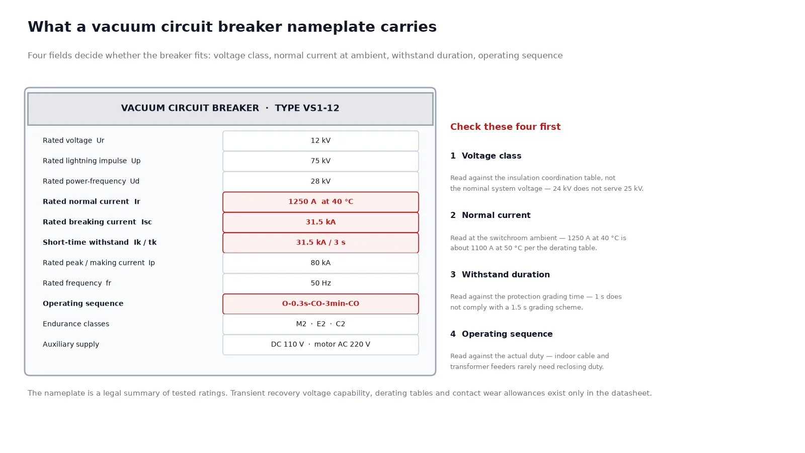
A vacuum circuit breaker nameplate carries about fourteen ratings, and most buyers read four of them. That is usually enough to place an order and not nearly enough to check one. The gap between the two is where ordering mistakes live: a breaker that is correct on rated current and short-circuit current but wrong on insulation level, wrong on operating sequence, or rated at a 40 degree ambient when the switchroom runs at 50.
The parameters are defined by IEC 62271-100 for AC circuit breakers above 1 kV, with national deviations in IEEE C37.04 and C37.06 practice. This guide reads a nameplate field by field, explains what each rating actually constrains, and points out the four or five values where a small misreading has a large consequence.
Quick answer: what the fourteen fields mean
A medium-voltage vacuum breaker nameplate typically lists rated voltage, rated insulation level, rated frequency, rated normal current, rated short-circuit breaking current, rated short-time withstand current with its duration, rated peak withstand and making current, rated operating sequence, and the mechanical and electrical endurance classes. The rest is auxiliary and environmental data.
| Nameplate field |
Symbol |
Typical value at 12 kV |
What it constrains |
| Rated voltage |
Ur |
12 kV |
The highest system voltage the insulation is designed for |
| Rated lightning impulse withstand |
Up |
75 kV peak |
Impulse coordination with the cable and the transformer BIL |
| Rated power-frequency withstand |
Ud |
28 kV rms |
One-minute AC withstand, proof of the insulation distance |
| Rated normal current |
Ir |
630 to 4000 A |
Continuous current at the rated ambient |
| Rated short-circuit breaking current |
Isc |
20 to 40 kA |
Largest fault the breaker can interrupt |
| Rated short-time withstand current |
Ik |
20 kA for 3 s |
Thermal duty while the fault is cleared by upstream protection |
| Rated peak withstand current |
Ip |
50 kA peak |
Electrodynamic duty on the first cycle |
| Rated operating sequence |
O-0.3s-CO-3min-CO |
as listed |
What the breaker can do in a reclose cycle |
| Mechanical endurance class |
M1 or M2 |
M2 typical |
Number of no-load operations before overhaul |
| Electrical endurance class |
E1 or E2 |
E2 typical |
Number of fault interruptions before contact replacement |
| Restrike class |
C1 or C2 |
C2 typical |
Probability of restrike during capacitive switching |
| Rated frequency |
fr |
50 Hz |
Governs the peak factor and the timing of everything else |
| Ambient temperature class |
minus 5 indoor and 40 |
as listed |
Current derating above the rated ambient |
| Rated auxiliary supply |
DC 110 / AC 220 V |
as listed |
Coil and motor compatibility with the station battery |
Rated voltage is not the system voltage
Ur is the highest voltage the insulation is designed to withstand continuously, which is why a 12 kV breaker is used on an 11 kV system and why a 24 kV breaker is used on a 20 kV system. The pairing follows the insulation coordination table, not the nominal system voltage. A 24 kV breaker does not cover a 25 kV system, because the highest voltage for equipment on that system exceeds 24 kV.
| Breaker rated voltage Ur |
Systems it serves |
Lightning impulse Up |
Power-frequency Ud |
| 7.2 kV |
6 kV, 6.6 kV |
60 kV |
20 kV |
| 12 kV |
10 kV, 11 kV |
75 kV |
28 kV |
| 17.5 kV |
13.8 kV, 15 kV |
95 kV |
38 kV |
| 24 kV |
20 kV, 22 kV |
125 kV |
50 kV |
| 36 kV |
33 kV, 34.5 kV, 35 kV |
170 kV |
70 kV |
| 40.5 kV |
35 kV, 36 kV where Up requires it |
185 kV |
80 kV |
The practical error here is ordering a 24 kV breaker for a 25 kV system because 24 looks close enough. It is not. The correct answer is a 36 kV or 40.5 kV frame. Our comparison of 10 kV, 11 kV and 13.8 kV voltage classes covers the same logic at the lower end of the range.
Rated normal current and the ambient question
Ir is the continuous current the breaker can carry at the rated ambient, which in IEC practice is 40 degrees Celsius maximum with a 24-hour average of 35. Above that, the breaker has to be derated. The derating is not a suggestion: the primary contacts, the tulip fingers and the enclosure all lose thermal margin together.
A breaker rated 1250 A at 40 degrees installed in a switchroom that reaches 50 degrees in summer is roughly an 1100 A breaker, and the exact figure comes from the manufacturer’s derating table rather than from a rule of thumb. Two things follow from this. First, when a switchgear room is air-conditioned only by ventilation, the design ambient should be stated explicitly in the enquiry. Second, if the load is expected to grow, the breaker is the cheapest place to buy margin, because replacing a breaker later is a busbar-level intervention.
Normal current is not thermal limit of the whole panel
The breaker rating is one link in the chain. Current transformers, cable terminations, busbars and the earthing switch all carry their own ratings, and the panel is only as capable as its weakest continuous element. A 4000 A breaker in a panel with 3150 A busbars is a 3150 A panel.
Short-circuit breaking current and the peak factor
Isc is the highest symmetrical fault current the breaker can interrupt. On a 12 kV distribution board this is commonly 20, 25 or 31.5 kA, set by the transformer impedance and the upstream network. Getting it too low is a safety problem; getting it much too high is simply money spent on capability the network cannot deliver.
The peak value is a separate rating because the mechanical stress on the first cycle is far higher than the symmetrical value suggests. IEC practice derives the peak from the symmetrical current using a factor that depends on the DC time constant:
- 50 Hz with a 45 ms time constant: Ip equals 2.5 times Ik.
- 60 Hz with a 45 ms time constant: Ip equals 2.6 times Ik.
- Longer time constants, common close to large generators, raise the factor further.
The rated making current is numerically the same peak value. A breaker that can make onto a fault it cannot break is not useful, and the two values on a nameplate are usually equal for that reason.
Short-time withstand current and its duration
Ik for tk seconds is what the breaker and its panel must survive while an upstream device clears the fault. On a typical distribution board that is 20 kA for 1 or 3 seconds. It matters because protection grading sometimes deliberately delays the local breaker so that a downstream device operates first, and during that delay the breaker carries fault current without breaking it.
The common specification mistake is to quote the breaking current and omit the duration. A 25 kA breaker with a one-second withstand is not the same product as a 25 kA breaker with a three-second withstand, and the second one costs more. If your protection study shows a grading time of 1.5 seconds, the one-second unit does not comply.
The operating sequence: the most misread line on the nameplate
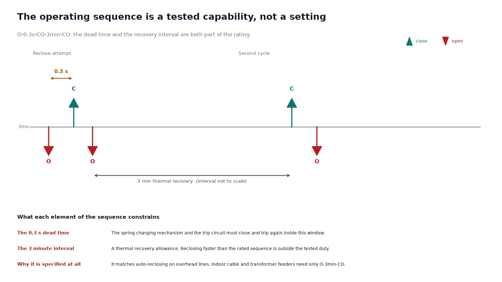
O-0.3s-CO-3min-CO means: open on fault, wait 0.3 seconds for the fault to clear or the line to de-energise, close and open again if the fault persists, then wait three minutes before the next close-open cycle. This is the auto-reclosing duty that overhead distribution practice requires.
Three things about that line matter:
- The 0.3 second dead time is the required capability, not a setting. The breaker must be able to close and trip again within that window, which is what the spring charging mechanism and the trip circuit are sized for.
- The three-minute interval is a thermal recovery allowance. A breaker that is reclosed faster than its rated sequence is outside its tested duty, whatever the mechanism allows.
- Indoor switchgear often does not need reclosing at all. If the panel feeds a transformer or a cable with no overhead section, a non-reclosing sequence of O-3min-CO is honest and cheaper. Specifying reclosing duty for an indoor panel buys capability that will never be used.
Endurance classes: mechanical, electrical and restrike
| Class |
Meaning |
Practical consequence |
| M1 |
Basic mechanical endurance, 2,000 operating cycles |
Sufficient for a network breaker operated a few times a week |
| M2 |
Extended mechanical endurance, 10,000 operating cycles |
Required for capacitor switching, frequent reconfiguration, or automated schemes |
| E1 |
Basic electrical endurance |
Few fault interruptions between contact inspections |
| E2 |
Extended electrical endurance |
Justified where the breaker clears faults repeatedly, such as a feeder with a high fault incidence |
| C1 |
Low probability of restrike during capacitive current switching |
Acceptable for general feeder duty |
| C2 |
Very low probability of restrike |
Required for capacitor bank and cable charging duty |
Vacuum interrupters normally reach C2 without difficulty, which is one reason vacuum displaced other technologies for capacitive switching. The class is still worth checking on the nameplate, because a C1 unit used on a capacitor bank is a service life problem that appears after a few hundred operations rather than on the first day.
Auxiliary data that trips up commissioning
The lower half of a nameplate is unglamorous and frequently the reason a panel cannot be commissioned on schedule:
- Closing and opening coil voltage and type. A DC 110 V coil on a station battery that sags to 85 V during a fault may fail to trip. Check the coil operating range, not just the nominal value.
- Spring charging motor supply. Motor voltage and power consumption determine the charger and battery sizing.
- Auxiliary contact configuration. The number of normally open and normally closed contacts must cover the indication, interlock and SCADA requirements, and adding a block later is a panel modification.
- Anti-pumping. Required wherever a persistent trip signal could cause repeated closing attempts. Confirm it is mechanical or electrical as the site standard requires.
- Enclosure protection and mechanical life of interlocks. For withdrawable units, the number of insertion and withdrawal cycles the interlock system is rated for belongs in the datasheet even when it does not appear on the nameplate.
Nameplate versus datasheet: what lives where
The nameplate is a legal summary. The datasheet carries the information you need in order to design around the breaker.
| Item |
On the nameplate |
Only in the datasheet |
| Rated voltage and insulation level |
Yes |
Clearance and creepage distances |
| Normal current |
Yes |
Derating table against ambient |
| Breaking and withstand current |
Yes |
Transient recovery voltage capability |
| Operating sequence |
Yes |
Spring charge time and closing time |
| Endurance class |
Yes |
Contact wear allowance and inspection intervals |
| Out-of-phase breaking current |
Rarely |
Commonly, as a percentage of Isc |
| Dimensions and mass |
No |
Required for panel layout |
The transient recovery voltage item is worth a comment. A breaker can be correctly rated on current and still be applied where the TRV is steeper than its tested capability, typically when the breaker is close-coupled to a transformer or a reactor. That is a system study output, and it is one of the few places where a technically compliant breaker is nonetheless the wrong choice.
Reading a nameplate in practice
The four checks worth doing before accepting a delivered breaker:
- Voltage class against the insulation coordination table, not against the nominal system voltage. This catches the 24 kV on a 25 kV system error.
- Normal current against the switchroom ambient, using the derating table. This catches the summer overload that appears two years later.
- Withstand duration against the protection grading time. This catches the one-second unit in a 1.5 second grading scheme.
- Operating sequence against the actual duty. This catches the reclosing breaker bought for an indoor cable feeder, and the non-reclosing breaker bought for an overhead line.
For the product side, the vacuum circuit breaker range lists the standard ratings and classes for each frame, and the VS1 series vacuum circuit breaker is the reference indoor unit for the 12 kV class. The VSG-12 indoor vacuum circuit breaker covers the same class in a different panel format, and the nameplate fields are identical, so the same reading method applies. If your application involves frequent switching rather than fault clearing, compare against the circuit breaker technical overview before fixing the endurance class, and read the fixed versus withdrawable comparison in our VS1 fixed and withdrawable guide when the panel arrangement is still open.
FAQ
What does 25 kA for 3 seconds mean on a breaker nameplate?
It is the rated short-time withstand current and its duration: the breaker can carry 25 kA rms of fault current for three seconds without damage, while an upstream device clears the fault. It is not the breaking capability, although on many breakers the two values are numerically equal. The duration is the part that is frequently omitted from specifications and quoted back inconsistently.
What is the difference between rated breaking current and rated making current?
Breaking current is what the breaker can interrupt once the fault current is flowing. Making current is the peak current the breaker can withstand when it closes onto an existing fault. Because the first-cycle peak is about 2.5 times the symmetrical rms value, the making rating appears much higher. Both are stress ratings; only the breaking rating is about arc interruption.
Why is the operating sequence O-0.3s-CO-3min-CO so common?
It matches auto-reclosing practice on overhead distribution networks, where most faults are transient and a fast reclose restores supply. The 0.3 second dead time is the tested capability, and the three minute interval allows thermal recovery before the next cycle. Indoor switchgear feeding cables or transformers usually does not need it.
Can I use a 630 A breaker for a 700 A load if the ambient is cool?
No. Derating works in one direction only: a breaker rated at 40 degrees can often carry slightly more in a cooler room, subject to the manufacturer’s table, but a breaker cannot be used above its rated current because the ambient happens to be low. The rating is the ceiling, not a starting point for negotiation.
What is class C2 and why does it matter for capacitor switching?
C2 is the very-low-restrike class for capacitive current switching. Restrikes produce high-frequency inrush and overvoltages that damage both the capacitor bank and the breaker. A C1 breaker on capacitor duty may appear to work for a long time before contact erosion and overvoltage damage become visible, which is why the class is specified rather than discovered.
Does the nameplate tell me the breaker is suitable for my fault level?
Only partly. The nameplate gives the breaking and withstand ratings; it does not give the transient recovery voltage capability, the actual system fault level, or the protection grading time. Those come from the network study. Comparing the nameplate against the study is the check that matters, and it needs both documents.
If you have the system voltage, fault level and protection grading time, send them and we will confirm which frame and rating class actually fits rather than the nearest standard unit.