A vacuum load break switch on its own cannot clear a fault. It can open under load, it can make onto a fault, and it can carry fault current for a defined time while something else clears it. That is exactly the role it plays in a switch-fuse combination: the switch handles normal operation and the fuse handles the fault.
The combination is the standard protective arrangement for distribution transformers in ring main units and compact secondary substations. It is cheaper than a circuit breaker with relays and a DC battery, it occupies less space, and for a defined window of transformer size and fault level it is technically sound. Outside that window it stops being sound, and the boundary is not a matter of opinion: it is set by two numbers that both appear on the equipment data sheets.
This guide explains what each device in the combination does, how the fuse and the switch are coordinated, where the combination is the right answer, and the specific failure mode that catches people out.
Quick answer
Use a vacuum load break switch with fuse combination where the protected transformer is up to roughly 1250 kVA at 12 kV or 2000 kVA at 24 kV, the prospective fault level does not exceed what the fuse can interrupt, and the duty is a distribution transformer that does not need auto-reclosing. Use a circuit breaker instead when the fault level is high, when downstream protection coordination must discriminate over a wide range, when remote control is required, or when the transformer is large enough that fuse selection stops being practical.
What the combination actually is
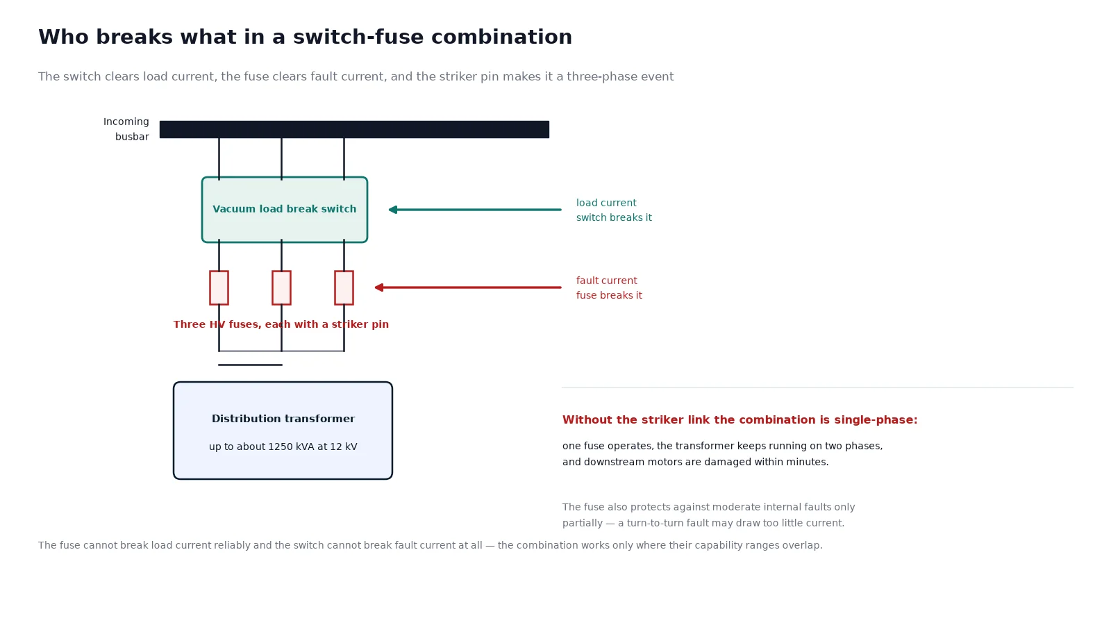
A switch-fuse combination per IEC 62271-105 comprises three elements working as one:
- The load break switch. Three-pole, usually vacuum, with a spring mechanism. It breaks rated normal current, cable charging current and, in ring configurations, closed-loop current. It has a rated short-time withstand current and a rated making current but no rated short-circuit breaking current.
- The high-voltage fuse. A current-limiting fuse per IEC 60282-1, sized to protect the transformer against fault current and to interrupt currents above the level the switch can break.
- The tripping link. A striker pin on the fuse that, when the fuse operates, releases the switch mechanism so that all three poles open. Without this, the combination is single-phase and the transformer runs on two phases.
The third element is the one buyers most often fail to verify, and it is the one that decides whether a fuse operation becomes a controlled outage or a motor burnout.
Who breaks what: the division of duty
| Duty |
Load break switch |
HV fuse |
| Rated normal current, continuous |
Carries it |
Carries it, below its rating |
| Load current interruption |
Breaks it |
Cannot break load current reliably |
| Cable charging and small inductive current |
Breaks it |
Not designed for it |
| Transformer magnetising inrush |
Makes it, does not break it |
Must ride through it without operating |
| Short-circuit current above the transfer level |
Carries briefly, does not break it |
Breaks it, current-limiting |
| Short-circuit current below the transfer level |
Breaks it |
Cannot break it reliably |
| Overload just above transformer rating |
Breaks it if switched manually |
May not operate, which is why thermal protection may still be needed |
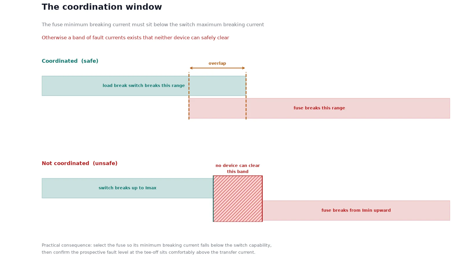
That table contains the whole logic of the combination. The switch is capable over the low-current end of the fault spectrum and the fuse is capable over the high-current end. For the arrangement to be safe, the two capability ranges must overlap.
The transfer current: the number that decides the application
Every fuse has a minimum breaking current. Below it, the fuse element may melt without being able to interrupt the resulting arc, which is a dangerous failure. Every load break switch has a maximum breaking current. Above it, the arc cannot be controlled.
The transfer current is the current at which these two limits meet. Below the transfer current, the switch is responsible; above it, the fuse is responsible. On a 12 kV combination this crossover typically falls in the range of several hundred amperes to about two thousand amperes, depending on the fuse rating and the switch design.
Two consequences follow directly:
- The fuse rating must be chosen so that its minimum breaking current is below the switch’s maximum breaking current. Otherwise there is a band of fault currents that neither device can safely clear.
- The prospective fault level at the transformer terminals must exceed the transfer current by a comfortable margin. If the available fault current at the installation is only slightly above the transformer full-load current, the combination sits in the region where coordination is fragile and a circuit breaker with a relay is more honest.
Where the combination is the right answer
The arrangement dominates three application types, and for good reasons in each.
Ring main units and compact secondary substations
An RMU typically has two ring switches and one or two tee-off ways. The tee-off protects a distribution transformer, and the fuse is the natural protective device because it needs no relay, no CTs, no auxiliary DC supply and no settings. That matters in a pad-mounted enclosure that may sit unvisited for years, where a battery would be a maintenance liability rather than a convenience.
Distribution transformers up to about 1250 kVA at 12 kV
Within this range the fuse current rating stays practical, the inrush withstand requirement is achievable, and the transfer current condition is normally satisfied on a network with a reasonable fault level. Above this size, fuses become large, inrush coordination becomes difficult, and the case for a breaker strengthens.
Installations without a reliable DC auxiliary supply
A circuit breaker needs a trip source. Where there is no station battery and no reliable AC auxiliary supply, a fuse needs nothing but the fault current itself. This is the single strongest argument for the combination in rural and remote distribution.
| Criterion |
Switch plus fuse |
Circuit breaker |
| First cost, 12 kV tee-off |
Lower |
Higher, plus relays and CTs |
| Footprint |
Compact |
Larger panel, relay compartment |
| Auxiliary supply needed |
None |
DC battery or reliable AC |
| Protection settings |
Fixed by fuse choice |
Adjustable, can be graded |
| Remote control and SCADA |
Limited |
Native |
| Auto-reclosing |
Not applicable |
Available |
| Fault level capability |
Bounded by fuse rating |
Bounded by breaker rating |
| Recovery after a fault |
Replace fuse, restore supply |
Reset and reclose |
| Earth fault sensitivity |
Depends on fuse and earthing |
Can be set precisely |
Where the combination stops working
Four conditions should push you toward a circuit breaker:
- High prospective fault level. The fuse must be able to interrupt the maximum fault current at its terminals. On a stiff urban network with a large upstream transformer, that requirement may exceed what a practical fuse rating can deliver.
- Wide coordination range. A fuse has one curve. Where the installation needs to discriminate against several downstream devices with different characteristics, an adjustable relay does the job better.
- Frequent fault interruption. Every fuse operation costs a fuse and a site visit. On a feeder with a high fault incidence, the maintenance cost overtakes the capital saving quickly.
- Large transformers. Above roughly 1250 kVA at 12 kV the fuse rating needed for inrush withstand and overload protection begins to conflict with the transfer current requirement, and the combination becomes a compromise rather than a solution.
Fuse selection: the three rules that matter
Fuse selection for a transformer tee-off is usually summarised as a multiple of full-load current. That is a starting point, not the method. Three conditions have to be satisfied simultaneously.
- Carry the load. The fuse rating must be above the transformer full-load current with margin for allowable overload. For distribution transformers a multiplier of roughly 1.5 to 2.5 times full-load current is common, depending on the loading policy and the ambient.
- Ride through inrush. Transformer energisation produces a magnetising inrush with a high peak and a decay of a few tenths of a second. The fuse must not operate on it, which is checked against the fuse manufacturer’s inrush withstand curve rather than against a rule of thumb.
- Coordinate with the transfer current. The fuse’s minimum breaking current must sit below the switch’s breaking capability, so that the two devices cover the whole fault range without a gap.
There is a fourth, less obvious condition: the fuse must also protect the transformer against internal faults of moderate current. A current-limiting fuse is fast at high current and slow at low current, so a turn-to-turn fault drawing only twice rated current may not be cleared at all. This is why some specifications add a thermal relay or an oil temperature trip even on a fused tee-off. Where the transformer is dry-type and indoors, that additional protection is usually worth the modest cost.
The single-phasing problem
This is the failure mode that makes the tripping link essential. If one fuse of the three operates and the other two remain intact, the transformer continues to be supplied on two phases. Motors downstream see a severe voltage imbalance, current in the remaining phases rises, and a motor can be damaged within minutes. The transformer itself is also subjected to negative-sequence current and local overheating.
Two design responses exist:
- Striker-pin tripping. The fuse carrier has a striker that, when the element operates, mechanically releases the switch so all three poles open. This is the standard arrangement and it should be verified on the actual product, not assumed from the catalogue description.
- Three-phase trip via a relay. Used where the combination is motorised and monitored. More capable, but it reintroduces the auxiliary supply the combination was meant to avoid.
If the switch does not trip all three poles on a fuse operation, the combination is not a three-phase protective device. Ask for the mechanism drawing and, if possible, witness the test.
Interlocks and operating safety
The combination is usually installed with an earthing switch, and the interlocks between the switch, the earthing switch and the fuse compartment door are what make the equipment safe to operate. The essentials:
- The earthing switch cannot be closed while the load break switch is closed.
- The load break switch cannot be closed while the earthing switch is closed, unless the design explicitly allows a making-proof earthing switch.
- The fuse compartment cannot be opened while the switch is closed, or the earthing switch is not in the earthed position.
- The cable compartment door cannot be opened without the earthing switch closed.
These interlocks are mechanical and therefore inspectable. During a factory acceptance test, operate each of them deliberately and confirm that the forbidden operation is actually blocked, rather than relying on the general arrangement drawing.
Combination specifics in practice
The VZFR-12 vacuum load break switch and fuse combination is the 12 kV reference unit in this class, built for ring main unit and compact substation tee-off duty. For the broader frame and rating matrix, the vacuum circuit breaker range lists the switch and breaker options side by side, and the technical overview at vacuum circuit breaker explains where the switch, the combination and the breaker each sit.
Where the project needs remote operation or precise grading, compare the VS1 series vacuum circuit breaker and the VBI-12 embedded pole vacuum circuit breaker against the combination before committing to a panel layout, because the auxiliary supply and relay compartment change the enclosure design. And when you are reading the ratings on the delivered equipment, our guide to vacuum circuit breaker nameplate parameters explains the withstand, making and sequence values that appear alongside the switch ratings.
FAQ
Can a load break switch clear a short circuit?
No. A load break switch is rated to break normal load current, cable charging current and, in ring configurations, closed-loop current. It has a rated short-time withstand current and a rated making current, but no rated short-circuit breaking current. Clearing fault current is the fuse’s job in a combination, or the breaker’s job in a breaker arrangement.
What is the transfer current in a switch-fuse combination?
It is the current at which the fuse takes over fault clearing duty from the switch. Below it, the switch can break the current; above it, the fuse can. For the combination to be safe, the fuse’s minimum breaking current must be below the switch’s maximum breaking current, so that the two capability ranges overlap rather than leave a gap.
Why must the switch trip all three phases when a fuse operates?
Because single-phasing damages motors and overheats the transformer. If one fuse operates and the other two do not, the transformer continues to be supplied on two phases. The striker pin on the fuse releases the switch mechanism so that all three poles open, converting a single-phase event into a controlled three-phase outage.
How do I size the fuse for a 1000 kVA 12 kV transformer?
Start from the full-load current, which is about 48 A at 11 kV for 1000 kVA, apply a multiplier in the range of roughly 1.5 to 2.5 depending on loading policy and ambient, then check the result against the fuse’s inrush withstand curve for the actual transformer. Finally verify the transfer current condition against the switch. The multiplier alone is not a selection method.
Is a switch-fuse combination suitable for a capacitor bank?
Generally no. Capacitor switching requires a device rated for capacitive breaking current with a defined restrike class, and the fuse is not a suitable interrupting device for capacitive current. Use a vacuum circuit breaker rated for capacitor bank duty, or a vacuum contactor designed for capacitor switching.
What happens after a fuse operates?
The switch opens via the striker link, the circuit goes dead, and the fault has to be found before the fuse is replaced. Fuse replacement requires the earthing switch closed and the compartment interlock released. This is why the combination suits installations where a fault is an occasional event rather than a routine one.
If you can provide the transformer rating, the system voltage and the prospective fault level at the tee-off, we will confirm whether the switch-fuse combination stays inside its coordination window or whether the application has moved into breaker territory.