ZW7-40.5 vs ZW32-40.5: 40.5kV Outdoor VCB Selection
ZW7-40.5 against ZW32-40.5: what 40.5 kV actually covers, rated current limits, fault level, platform versus structure mounting and CT provision.
Read More

Fitting a vacuum circuit breaker into KYN28 switchgear is not difficult. It is unforgiving. The panel is a metal-clad, factory-assembled assembly in which the breaker travels on a truck between a test position and a service position, and every one of the safety functions in the panel depends on the interlocks being correct and the clearances being what the design says. Get the mechanical sequence wrong and the panel will still close, still carry load, and still look fine — until someone tries to rack the truck in with the breaker closed.
KYN28A-12 is the most widely built 12 kV metal-clad withdrawable panel type in Chinese-standard projects and it travels into a great many export substations. This guide covers the compartment arrangement, the five interlocks that define the design, the clearances that actually matter, and the commissioning checks that catch the errors which survive a visual inspection.
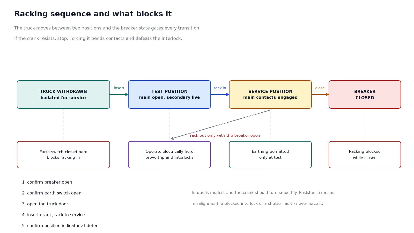
A KYN28 panel is divided into four compartments: a busbar compartment at the top rear, a breaker or truck compartment in the middle front, a cable compartment at the bottom rear, and a low-voltage or relay compartment at the front above the truck. The truck moves horizontally between a test position, where the main contacts are separated but the auxiliary contacts remain connected, and a service position, where the main contacts engage. Five mechanical interlocks enforce the order in which that movement and the breaker can be operated, and they are what make the panel safe to work on.
| Compartment | Position | Contents | Access |
|---|---|---|---|
| Busbar | Top rear | Main busbars, branch busbars, shutters | Bolted cover, interlocked with the truck position |
| Breaker / truck | Middle front | VCB on a withdrawable truck, racking mechanism | Door opens only at test position |
| Cable | Bottom rear | Cable terminations, surge arresters, current transformers, earth switch | Bolted cover or interlocked door |
| Relay / LV | Front upper | Protection relay, meters, control terminals, test block | Hinged door, no live main circuit |
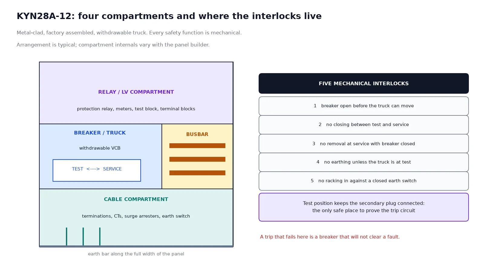
Different manufacturers number them differently and describe them in different words. The functions are the same, and each exists because someone once did the thing it prevents.
One: the breaker must be open before the truck can move. Racking is mechanically blocked while the breaker is closed. This is the interlock that keeps a load current from being interrupted by drawing an arc across the main contacts as they separate at low speed — which is not an interruption, it is a fault.
Two: the breaker cannot be closed unless the truck is fully in the test or the service position. A truck stopped halfway has the main contacts neither fully engaged nor fully separated, and closing in that condition produces an arc on the contact tips with no arc control. The interlock is tied to the racking mechanism position rather than to the door.
Three: the truck cannot be removed from the service position while the breaker is closed. This is the same function as the first interlock seen from the other direction, and on most designs it is implemented by the same linkage. It matters because the racking crank can be applied by someone who has not checked the position indicator.
Four: the earthing switch cannot be closed unless the truck is in the test position. Earthing the cable side while the breaker is in service would connect the live busbar to earth through the closed breaker. The interlock enforces the isolation before the earth.
Five: the truck cannot be racked in while the earthing switch is closed. This is the one that gets defeated most often during commissioning, because the earth switch is sometimes closed for the cable test and left closed. Racking in against a closed earth switch produces a three-phase earth fault at the moment the main contacts engage.
Beyond the five, most panels include a shutter mechanism that closes over the busbar and cable spouts when the truck is withdrawn, and a voltage presence indication with a capacitive divider on the cable side. Neither is an interlock in the strict sense, but both are part of the safety case and both need to be checked during commissioning rather than assumed.
The IEC 62271-200 minimum air clearance for the 12 kV class is 125 mm phase-to-phase and phase-to-earth. That is the floor, and a panel designed to the floor is a different product from a panel designed with margin. KYN28 panels in normal production typically provide 210 mm busbar phase centres and a 125 mm minimum in the truck compartment, with the actual values stated on the manufacturer’s drawing.
| Location | Typical design value at 12 kV | Comment |
|---|---|---|
| Busbar phase centres | 210 mm | Set by the busbar supports and the joint bolts |
| Minimum phase-to-earth in air | 125 mm | The standard floor; do not accept less |
| Between live parts and the truck shutter | Depends on truck position | Checked at the test position, not the service position |
| Cable termination to compartment wall | Set by the termination type | T-connectors change this value |
| Busbar to top cover | Governed by the pressure relief design | Do not reduce for cable routing |
The clearance failure that actually happens in the field is not a manufacturing defect. It is a field modification: a cable lug that projects further than the design allowed, a CT added to the cable side that was not in the original arrangement, or a surge arrester mounted where the cable bend radius was supposed to be. Each of those reduces a distance that was calculated once and never re-checked.
The racking sequence itself is short. Confirm the breaker is open, confirm the earth switch is open, open the truck compartment door, insert the crank, and turn until the position indicator reaches service and the mechanism reaches its detent. The torque required is modest and the crank should turn smoothly. If it does not, stop: a mechanism that resists is either misaligned, blocked by an interlock, or has a shutter problem, and forcing it is how contacts get bent.
The test position is the one that gets under-used. In the test position the main contacts are separated but the secondary plug is still connected, which means the breaker can be operated electrically with the main circuit isolated. That is the position for proving the protection, the trip circuit and the interlocks before the panel is ever put into service. A commissioning programme that goes straight to service and tests the trip from there has skipped the only safe opportunity to prove the trip circuit.
Most installation problems at this level are not in the breaker. They are in the connections around it.
Cable terminations. The cable compartment height determines the maximum termination height above the floor and therefore the cable bending radius. A 240 mm² single-core cable needs a bend radius that is often larger than the space available if the termination is at the top of the compartment. Decide the termination type — porcelain, heat-shrink or separable connector — before the panel is ordered, because it changes the compartment internals.
Current transformers. Cable-side CTs are usually mounted on the bushings below the truck. Their ratio and class have to be fixed at ordering, and a zero-sequence core, if the protection scheme needs one, is a separate core with its own window. Adding a core later is not a field operation.
Earthing. The truck’s earthing contact engages a fixed earth bar as it reaches the service position. That sliding contact has to be clean and correctly tensioned, because it is the fault current path. Check it with the truck racked in and the panel isolated, and check the earth bar continuity to the station earth grid separately.
Pressure relief. An arc-rated panel has a pressure relief flap or duct, usually at the top or rear. It must not be obstructed by cable trays, conduit or a wall. Panels installed against a wall with the relief duct facing it are a recurring finding in arc-rated installations.
| Check | Method | Pass criterion |
|---|---|---|
| Interlock one | Attempt racking with breaker closed | Mechanism blocked, no movement |
| Interlock two | Attempt close with truck between positions | Close circuit open, no operation |
| Interlock four | Attempt earth switch closure at service position | Blocked |
| Interlock five | Attempt racking in with earth switch closed | Blocked |
| Shutter operation | Rack out and observe spouts | Both shutters close fully and independently |
| Trip circuit | Operate from the protection relay at test position | Breaker trips on first command |
| Secondary plug | Check engagement and retention | Fully seated, no partial contact |
| Earth contact resistance | Micro-ohm meter across the sliding contact | Within the manufacturer’s limit |
| Pressure relief path | Visual inspection of the duct | Unobstructed to free air |
| Clearances after modification | Measure any field-added component | At or above the drawing value |
The trip circuit test at the test position is the single most valuable item on that list. A breaker that will not trip is a breaker that will not clear a fault, and the trip circuit goes through the secondary plug, the auxiliary contacts and the protection output — three connections that are all proven by one operation.
KYN28 is a withdrawable design by definition, but not every bay needs that. A fixed breaker in a panel is cheaper and occupies less depth, and it gives up the ability to isolate and remove the breaker without opening the cable compartment. Where the panel is a motor starter or a rarely operated feeder, fixed is often correct; where it is a main incomer or a bus section that has to be restored quickly, withdrawable earns its cost. The trade-off is set out in our comparison of fixed and withdrawable VS1 breakers, and it is worth settling before the panel order because it changes the whole arrangement.
For the breaker itself, the VSG-12 indoor vacuum circuit breaker is the common truck unit for this panel type at 12 kV, and the VBI-12 covers the same class in a different mechanical format. The rating fields that have to match the panel — rated current, breaking current, and the operating sequence — are explained in the nameplate guide. Where the panel is part of a complete substation package, the switchgear and substation solutions page covers the arrangement, and the full vacuum circuit breaker range lists every indoor frame with its truck compatibility.
It is a Chinese-standard designation rather than an IEC one: K for enclosed, Y for withdrawable, N for indoor and 28 for the design series, with the following number giving the voltage class. KYN28A-12 is therefore an indoor, enclosed, withdrawable panel for the 12 kV class. The IEC equivalent description is metal-clad factory-assembled switchgear, and the ratings are declared against IEC 62271-200.
Five mechanical interlocks that matter for operation, plus the shutter mechanism and the voltage presence indication. The five enforce: open breaker before racking, no closing between positions, no removal at service with the breaker closed, no earthing while in service, and no racking in against a closed earth switch.
The interlock is designed to prevent it and a correctly maintained panel will block the crank. If the crank turns with the breaker closed, the interlock is defective and the panel must be taken out of service. Do not test this on a live panel as a function check — do it during commissioning with the panel isolated.
It separates the main contacts while keeping the secondary circuit connected, so the breaker can be operated and the protection and trip circuit proven with the main circuit isolated. It is the only safe position for that test, and skipping it is the most common commissioning shortcut.
The IEC 62271-200 minimum is 125 mm phase-to-phase and phase-to-earth. Production panels usually provide more at the busbars — 210 mm phase centres is typical for KYN28 — and the design values are on the manufacturer’s drawing. Field modifications are what usually reduce a clearance below the drawing value.
Usually the secondary plug is not fully engaged, or the auxiliary contact that proves the truck position is not closed, so the protection output has nowhere to go. Both are mechanical seating problems rather than wiring problems, and both are found by checking the plug engagement before blaming the relay.
Send the panel arrangement, the breaker rating and the cable termination type, and we will confirm the truck compatibility and the compartment internals before the order is fixed.