The 40.5 kV class is where distribution ends and sub-transmission begins, and it is the voltage level where the difference between two outdoor breakers stops being a matter of preference and becomes a matter of substation layout. ZW7-40.5 and ZW32-40.5 are both three-phase outdoor vacuum breakers in that class. One is a tank unit designed to sit on a concrete platform and be inspected from the ground. The other is a pole unit designed to be lifted onto a structure and operated from a truck.
Choosing between them wrongly is expensive in a way that a 12 kV mistake is not, because at 40.5 kV the structure, the foundation and the clearance envelope are all part of the decision. This guide covers the voltage class itself first — because 35 kV is not one thing across national standards — then compares the two frames, and ends with the layout consequences that decide most projects.
First: what 40.5 kV actually covers
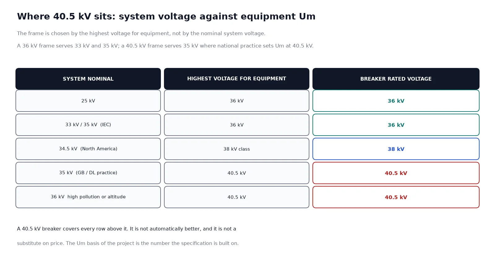
Rated voltage is not system voltage. A breaker is rated at the highest voltage for equipment (Um) of the system it serves, and that number is set by national standard practice rather than by the nominal figure. In Chinese practice a 35 kV system has an Um of 40.5 kV, so 40.5 kV equipment is the ordinary choice and 36 kV equipment is not. In IEC practice a 33 kV or 35 kV system has an Um of 36 kV, so 36 kV equipment is normal and 40.5 kV is the upgrade. North American 34.5 kV usually goes to 38 kV class equipment.
| System nominal voltage |
Highest voltage for equipment (Um) |
Breaker rated voltage |
Lightning impulse Up |
Power-frequency Ud |
| 25 kV |
36 kV |
36 kV |
170 kV |
70 kV |
| 33 kV, 35 kV (IEC) |
36 kV |
36 kV |
170 kV |
70 kV |
| 34.5 kV (North America) |
38 kV class |
38 kV |
150 kV |
80 kV |
| 35 kV (Chinese GB practice) |
40.5 kV |
40.5 kV |
185 kV |
80 kV |
| 36 kV where pollution or altitude requires |
40.5 kV |
40.5 kV |
185 kV |
80 kV |
The practical consequence is that a 40.5 kV breaker is not automatically “better” than a 36 kV one and does not automatically substitute for it on price. It is the correct unit where the system Um is 40.5 kV, and it is an upgrade where the system Um is 36 kV and something — pollution, altitude, or a specification that simply asks for margin — justifies the larger insulation envelope. Our note on how voltage classes map to frames covers the same logic at the lower end of the range, and it is worth reading before assuming a 24 kV frame will cover 25 kV.
The two frames, compared
ZW7-40.5 is a three-phase common tank design: the interrupters sit in one tank, the bushings come out of the top, current transformers are inside the tank, and the spring mechanism is in a housing on the front. It is built to be bolted to a foundation or a steel platform and operated from ground level. Typical ratings run from 1250 A to 2000 A with breaking currents of 25 kA to 31.5 kA.
ZW32-40.5 is a pole-mounted design: cast insulation poles around the interrupters, a smaller tank, lower weight, and a form factor meant for a structure rather than a foundation. Typical ratings centre on 1250 A with breaking currents around 25 kA, and the unit is designed for the same pole-mounting practice as its 12 kV and 24 kV relatives.
| Parameter |
ZW7-40.5 |
ZW32-40.5 |
| Mounting |
Foundation or steel platform |
Pole or structure bracket |
| Construction |
Common tank with bushings |
Cast poles with interrupter inside |
| Typical rated current |
1250 A to 2000 A |
630 A to 1250 A |
| Typical breaking current |
25 kA to 31.5 kA |
25 kA |
| Current transformers |
Integrated, multi-core |
Variant-dependent; external CTs common |
| Weight |
Substantially heavier, foundation class |
Light enough for structure mounting |
| Operating access |
Front panel at working height |
Depends on structure height |
| Typical application |
Substation bay, line section on a platform |
Pole-top sectionalisers and branches |
| Earthing switch |
Commonly integrated |
Separate or optional depending on variant |
Layout decides more than the data sheet
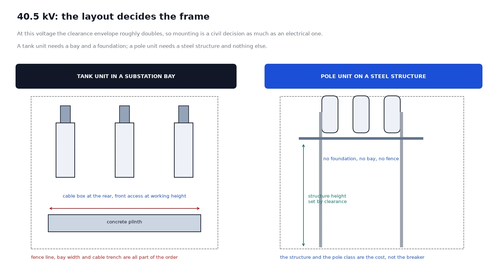
At 12 kV the two designs are largely interchangeable because a pole bracket can carry either. At 40.5 kV the clearance envelope grows with the square of the voltage, and that changes what “mounting” means.
Phase-to-phase and phase-to-earth clearances for a 40.5 kV outdoor installation are roughly twice what 12 kV requires, and the bushing height adds to that. A tank unit on a foundation needs a bay width that accommodates the clearances to adjacent equipment and a fence line that accommodates the unit’s own envelope. A pole unit needs a structure tall enough to hold the unit at the required clearance above ground, which at this voltage means a steel structure rather than a wooden pole in most cases.
Both are legitimate. But a project that already has a platform and a cable termination point is a platform project, and forcing a pole-mounted unit into it adds a steel structure that nobody designed for. A project that is a line sectionalisers programme across fifty poles is a pole project, and putting a tank breaker on a foundation at each of them multiplies civil works by fifty.
Rated current: where the two diverge most
2000 A is not available in the pole-mounted format. That single fact decides a large share of 40.5 kV projects. A substation incomer feeding a 20 MVA transformer at 35 kV carries roughly 330 A, so current is not the constraint; but a bus section or a line that carries the combined load of two transformers can approach or exceed 1250 A, and then the tank unit is the only option.
The other direction matters too. Specifying a 2000 A tank breaker on a pole-mounted branch that carries 300 A buys nothing except a heavier structure, a bigger foundation enquiry, and a longer delivery. The rated current should come from the load study with the design margin, and the frame should follow, not lead.
Fault level, breaking capacity and the loop question
At 40.5 kV the fault level near a substation is set by the upstream transformer and can reach the top of the class, particularly on a bus section where two sources can feed a fault through the closed bus. A 25 kA unit is adequate for most feeder positions; it is not adequate for a bus section where the combined contribution exceeds 25 kA. The calculation, not the catalogue, decides.
This is also where a load break switch stops being an option. At 40.5 kV, load break switches with fuses are used on transformer bays where the fuse covers the fault, but they cannot interrupt a bus fault. The combination is covered in our guide to the load break switch and fuse combination, and it is worth checking whether a bay actually needs a breaker before specifying one for fifty sites.
Earthing, interlocking and the safety case
An outdoor 40.5 kV breaker normally forms part of an isolation and earthing procedure, and the earthing switch is part of the safety case rather than an accessory. Where the breaker has an integrated earthing switch, the interlocks are mechanical and part of the product. Where the earthing is done with separate portable equipment, the procedure depends on the site’s safety rules and on the visible break, which a tank breaker does not provide and a pole breaker provides only from certain angles.
Ask the question explicitly: how is the circuit proved dead and earthed at this installation? The answer sometimes moves the choice, because a design that requires a visible break and an integrated earth switch is not served by the same unit as one that relies on a downstream isolator.
Decision matrix
| Project condition |
Preferred frame |
Reason |
| Rated current above 1250 A |
ZW7-40.5 |
The pole format does not go that high |
| Breaking current above 25 kA |
ZW7-40.5 |
Higher frames available in the tank design |
| Substation bay with cable terminations |
ZW7-40.5 |
Foundation, front access, integrated CTs |
| Line sectionalisers across many poles |
ZW32-40.5 |
No civil works per site, lighter structure |
| Revenue metering at the point |
ZW7-40.5 |
Multi-core CTs inside the tank |
| Temporary or relocatable installation |
ZW32-40.5 |
Lighter, no foundation |
| Site where all equipment is on one platform |
ZW7-40.5 |
Consistent layout and access |
| Retrofit onto an existing structure |
ZW32-40.5 |
Weight and bracket compatibility |
Specifying without a return visit
Six items settle it: the system nominal voltage and its Um basis (36 kV or 40.5 kV), the calculated fault level at the point, the load current with design margin, whether CTs are required and with what cores and classes, the installation arrangement — platform or structure — and the pollution severity. Add the control supply and whether remote operation is required, and the enquiry is complete.
For frames and ratings, the ZW7-40.5 outdoor vacuum circuit breaker page covers the platform-mounted range up to 2000 A, and the ZW32-40.5 series covers the pole-mounted frames. If the same project has 12 kV or 24 kV sections, the equivalent comparison at that level is our ZW8-12G and ZW32 comparison, the three-frame overview is our VS1, ZW32 and ZW7 comparison, the rating fields are explained in the nameplate guide, and the full vacuum circuit breaker range lists every outdoor frame with its class.
FAQ
Is a 40.5 kV breaker a substitute for a 36 kV breaker?
It covers every system a 36 kV breaker covers, with a larger insulation envelope and usually a higher price and a larger footprint. It is the correct and often mandatory choice where the national standard sets Um at 40.5 kV for a 35 kV system. Where the standard sets Um at 36 kV, a 40.5 kV unit is an upgrade that has to be justified by pollution, altitude or specification margin.
Can a 36 kV breaker be used on a 35 kV system?
Yes where the system Um is 36 kV, which is normal IEC practice. Not where the national practice sets Um at 40.5 kV, because the insulation coordination is then defined against the higher value. Confirm the Um basis of the project rather than the nominal voltage, because that is the number the specification is built on.
Why can’t I get 2000 A in a pole-mounted 40.5 kV breaker?
Because the pole-mounted format has no room for the larger contact structure and the heat path, and the structure that would have to carry it at 40.5 kV clearances is no longer a pole. Above 1250 A the tank design is the practical answer, and it comes with a foundation rather than a bracket.
Do I need an integrated earthing switch?
If the site’s isolation procedure depends on a mechanical earth on the breaker itself, yes, and the interlocks come with it. If earthing is done with separate portable equipment and the procedure is written that way, the earth switch is optional. The decision belongs to the safety case, not to the quotation.
How does pollution affect the choice at 40.5 kV?
More than at 12 kV, because the creepage distance scales with voltage and a polluted shed at 40.5 kV has far more surface to track across. Specify the creepage distance against IEC 60815 for the site severity and check whether the design meets it, rather than relying on the construction type. In heavy pollution the larger tank unit with long bushings is often the more comfortable choice.
What is the typical operating sequence at this level?
O-0.3s-CO-3min-CO is standard and matches auto-reclosing practice on overhead lines at this voltage. Confirm that the mechanism can recharge inside the dead time; a motor-charged spring mechanism that needs 12 seconds cannot complete the second close without a capacitor-assisted close. The sequence is on the nameplate and it is a tested capability, not a nominal one.
Send the Um basis, fault level, load current and installation arrangement, and we will confirm one frame with the CT specification rather than a shortlist.