LZZBW-35 Outdoor CT for 35kV Metering
Ratio, 0.2S accuracy, burden and pollution class decide a 35 kV outdoor current transformer. What LZZBW-35 means and how cast resin compares with oil.
Read More

A capacitor bank is the most punishing load a contactor will ever see. The steady-state current is modest, often less than a motor of the same frame size would draw, but the instant of closing produces a current spike that can reach tens of times that value at a frequency of several kilohertz. A contactor chosen on steady-state amps alone will weld its contacts within a few hundred operations, and the failure usually takes the capacitor fuses with it.
This guide covers what a capacitor switching contactor has to survive on a medium-voltage network, how to calculate the current from the bank rating in kVAR, what a series reactor changes, and how to lay out the switching device, the reactor and the protection so the bank lives as long as the switchgear. If the frame itself is still open, the vacuum contactor range covers 160 A to 630 A across the 7.2 kV and 12 kV classes.
Power factor correction switching is usually described as an inrush problem. In practice three separate stresses act on the same device, and each has a different fix.
Vacuum interrupters handle the third stress well, which is why they displaced oil and air-break devices for this duty. The first two are handled by the circuit around the interrupter, not by the interrupter itself.
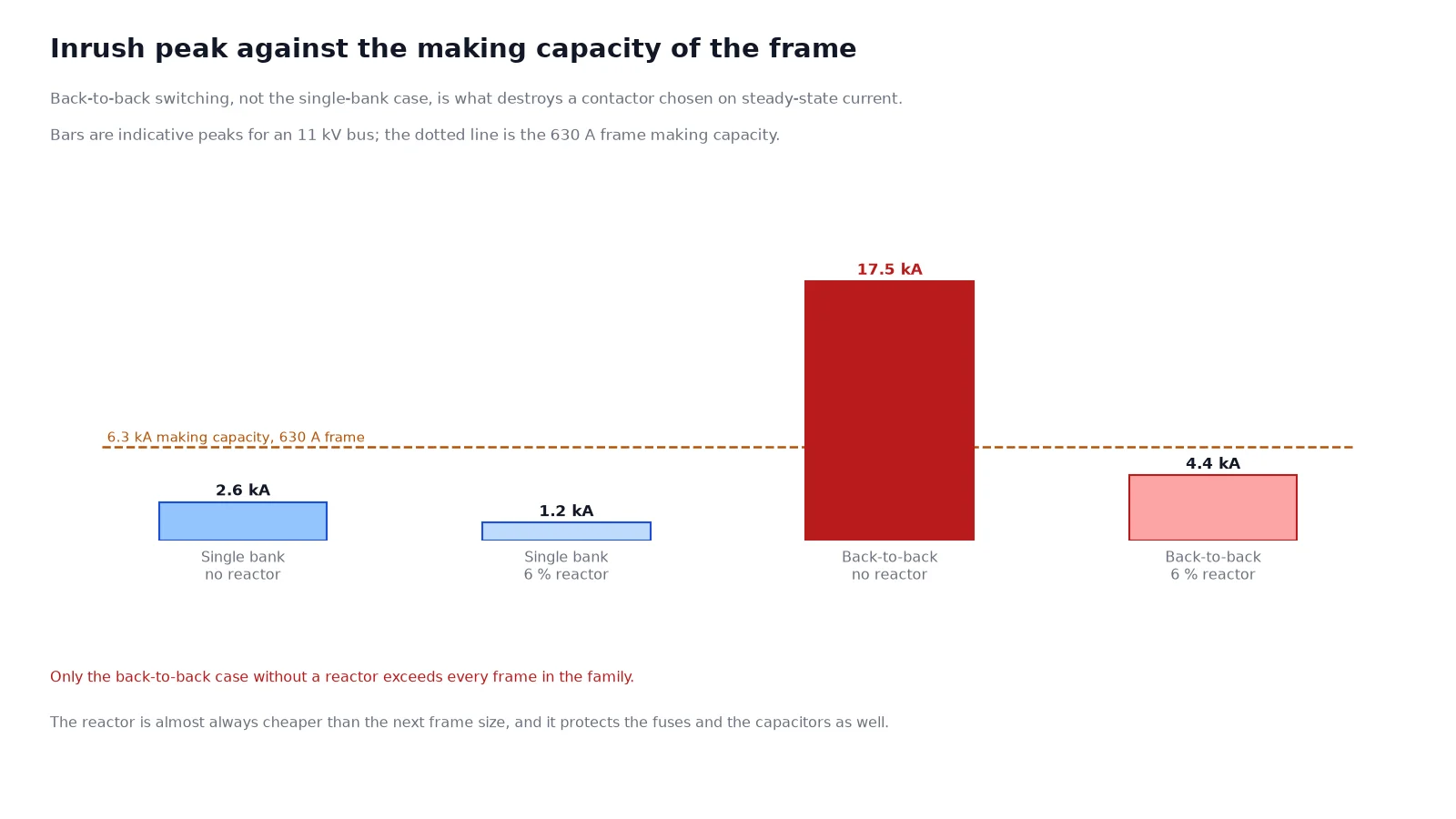
For a single isolated bank the inrush peak depends on the short-circuit level at the bus and the inductance of the cable run. On a typical 11 kV industrial bus with a few metres of cable between the contactor and the capacitor, the peak is a few kiloamperes at a frequency of a few hundred hertz. That is already several times the steady-state current, and it is the number the making capacity has to cover.
Back-to-back switching is a different order of magnitude. The inductance between two adjacent capacitor steps is measured in microhenries, the capacitance is large, and the resulting discharge oscillates at kilohertz with peaks that can exceed the short-circuit current of the bus. A contactor that closes a single bank without complaint will fail quickly when it closes into a bank that sits next to a charged one.
| Situation | Peak current | Frequency | Practical control |
|---|---|---|---|
| Single bank, long cable, weak bus | Low multiple of steady state | Hundreds of hertz | Contact making capacity is usually sufficient |
| Single bank, short cable, strong bus | Several kiloamperes | Few hundred hertz to 1 kHz | Check making capacity against the calculated peak |
| Back-to-back, no reactor | Highest, often limited by the device | Several kilohertz | Series reactor or a dedicated capacitor-switching device |
| Back-to-back, with 6 percent reactor | Reduced by roughly the reactor impedance ratio | Lower, and damped | Standard practice on multi-step MV banks |
The design rule that follows is simple. Any bank built in more than one step needs a reactor or a switching device rated for the back-to-back case. The reactor is almost always the cheaper of the two.
Capacitor banks are bought in kVAR and contactors in amperes, and the conversion is the first place where banks are under-sized. For a three-phase bank the steady-state current is the reactive power divided by root three times the line voltage.
| Bank rating | Current at 7.2 kV | Current at 11 kV | Current at 12 kV |
|---|---|---|---|
| 600 kVAR | 48 A | 31 A | 29 A |
| 1,000 kVAR | 80 A | 52 A | 48 A |
| 2,000 kVAR | 160 A | 105 A | 96 A |
| 3,000 kVAR | 241 A | 157 A | 144 A |
| 5,000 kVAR | 401 A | 262 A | 241 A |
Three corrections then apply, and each pushes the current up rather than down.
Take a 2,000 kVAR bank at 11 kV. The fundamental current is 105 A. Applying a capacitor tolerance, a voltage allowance and a harmonic allowance lands somewhere near 150 A, which points to the 250 A frame rather than the 160 A frame that the nominal figure suggested. Choosing on the nominal number is how banks end up on a contactor that is technically adequate and thermally marginal.
A reactor in series with the bank adds inductance to the loop the inrush current has to flow through, which limits the peak and lowers its frequency. Two ratings are common on medium-voltage banks.
| Reactance | What it is for | Effect on the bank |
|---|---|---|
| Around 6 percent | Inrush limiting and detuning below the fifth harmonic | Voltage across the capacitor rises by about 6 percent, so the capacitor must be rated for it |
| Around 13 percent | Detuning below the third harmonic, networks with heavy single-phase or converter load | Higher capacitor voltage rise and higher losses; frame current rises again |
The voltage consequence is the part buyers miss. The capacitor sees the system voltage plus the reactor drop, so a 6 percent reactor on an 11 kV bus requires capacitors rated near 11.7 kV. Ordering standard 11 kV capacitors behind a 6 percent reactor derates the bank and shortens its life. The contactor, meanwhile, carries the same current as the bank plus the reactive current of the reactor, which is why a reactor-fed bank needs the frame checked again after the reactor is added.
Capacitor duty is decided by making capacity. On a CKG3 frame the 7.2 kV build publishes a making capacity of 1,600 A on the 160 A frame up to 6,300 A on the 630 A frame for 100 operations, with a breaking capacity of 1,280 A to 5,000 A for 10 operations. Those ratios, roughly ten times rated current, are what makes the frame suitable for inductive motor duty with a high starting current.
Compare that with the calculated inrush of a back-to-back bank and the reason for the reactor becomes obvious. Without one, the peak can exceed the making capacity of every frame in the family. With one, the peak falls back inside the published envelope and the frame is chosen on thermal current again.
The published ratings for each build are on the CKG3 7.2 kV contactor and the CKG3 12 kV contactor pages, and the two builds are not interchangeable: the contact gap grows from 4 mm to 5.5 mm and the mechanical life drops from one million operations to 500,000. Where the bank sits on a 10 kV nominal system with 12 kV equipment, that difference matters, and the voltage class guide explains which nominal systems map to which equipment rating. If the alternative frames are still in play, the CKG3, CKJ5 and JCZ5 comparison shows where the medium-voltage and low-voltage designs divide.
When a contactor opens a capacitive circuit, the capacitor keeps its charge and the system voltage continues to oscillate. If the contact gap breaks down during the recovery, the capacitor is re-energised at a moment when its trapped voltage opposes the source. The resulting transient can reach two to three times normal peak voltage, and repeated occurrences destroy capacitor dielectric.
Modern vacuum interrupters are effectively restrike-free in capacitor duty when they are applied within their rating, but “effectively” is not “never”. Two measures are standard on medium-voltage banks: a surge arrester at the capacitor terminals, and a switching device whose capacitive breaking current is stated by the manufacturer rather than inferred from the motor rating. Do not accept a quotation that lists only the motor duty figures for a capacitor application.
A contactor suits a bank that is switched a few times a day for base correction. An automatic power factor controller that hunts, closing and opening steps every few minutes, will exhaust the operations budget of any contactor long before its calendar life. The CKG3 frame publishes 300 operations per hour mechanically and one million operations mechanically, with a mechanical-latch life of 100,000 operations for the latched version.
Two control practices extend the life of a stepping bank considerably. Set a dead band and a time delay in the controller so steps do not cycle on small changes in load, and rotate which step is switched first so the operations count is shared across the bank instead of falling on step one.
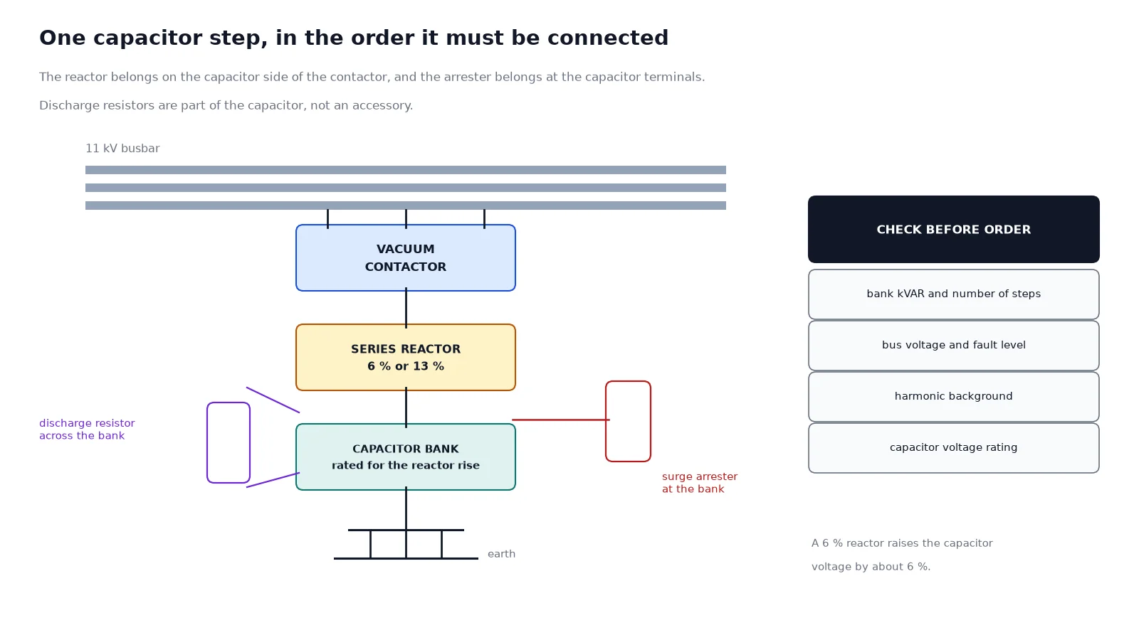
Sizing on nominal current is the first, and it appears on most under-performing installations. Omitting the reactor on a multi-step bank is the second. Third is ordering standard-voltage capacitors behind a detuned reactor, which derates the bank and quietly raises the current per kVAR. Fourth is using the motor duty figure as the capacitor breaking capacity, which is a documentation error that only shows up when the bank is switched under fault conditions.
Only if the calculated inrush, including the back-to-back case, falls inside the published making capacity, and only if the manufacturer states a capacitive breaking current. On multi-step banks without reactors it usually does not, and the contacts fail early.
Because the failure is caused by making inrush rather than by thermal current. Check the reactor, the number of parallel steps and the making capacity of the frame before replacing the contactor with the same model.
Not always. A single bank on a long cable from a weak bus may be fine without one. Calculate the peak first; if it sits comfortably inside the making capacity, the reactor buys margin but is not mandatory.
A contactor is the cheaper frequent-switching device and suits stepped correction. A circuit breaker is used where the bank also needs fault protection or where the switching frequency is low and the breaker is already in the circuit. See the comparison of vacuum contactors and breakers for the boundary.
Calculate the fundamental current from kVAR, add the reactor current, then apply the capacitor tolerance and harmonic margins. In practice the frame lands one size above the plain bank, which is why detuned banks should be specified with the reactor from the start.
The discharge resistors bring the bank down to a safe level within the time stated on the capacitor data sheet, commonly under a minute. The control logic must enforce an interval at least that long before the step can be closed again.
If you have the bank rating, the bus voltage, the number of steps and the harmonic environment, send those four items with the enquiry. The reactor, the frame and the switching device can then be matched as a set rather than chosen step by step, which is how capacitor installations avoid the second and third contactor replacement. Send the bank data to our engineers and the frame can be quoted against your actual inrush rather than a nominal figure.