Voltage transformer selection in three decisions
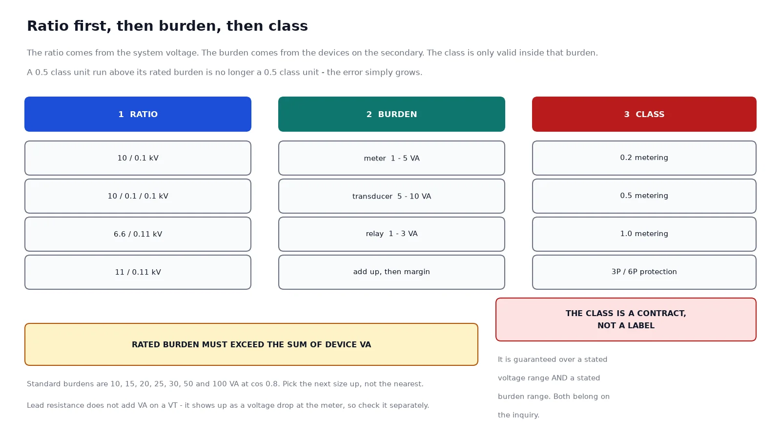
Choosing a voltage transformer looks like a single decision and is actually three, taken in a fixed order. The ratio comes from the system voltage and how the units are connected. The burden comes from the devices hanging on the secondary. The accuracy class comes last, because a class is only a promise inside the burden you just calculated. Get the order wrong – typically by picking a class first because a tender lists one – and the unit will be delivered to a specification that cannot be met in service.
This guide walks the three decisions in order, then adds the two conditions that override all of them: the earthing method and the voltage factor. It assumes an inductive voltage transformer to IEC 61869-3 in a medium-voltage panel, which covers most of what is ordered between 6 kV and 35 kV. The frames themselves are indexed in the voltage transformer range.
Step one: the ratio, and why it depends on connection
The primary rated voltage is not simply the system voltage. It depends on whether the unit is connected phase-to-earth or phase-to-phase, and on how many units make up the set.
Three single-phase units connected in star, with their primary star point earthed, each see the phase-to-earth voltage. On a 10 kV system that is 10 divided by root 3, about 5.77 kV, and the secondary is 0.1 divided by root 3, about 57.7 V. Three of those in star give the standard 100 V line-to-line at the meter, and the same set also gives you a per-phase voltage the relay can use for earth-fault logic.
Two units connected in open delta, sometimes called V-V, see the phase-to-phase voltage, so a 10 kV system takes a 10/0.1 kV ratio. This saves one unit and one primary fuse, and it costs you the per-phase measurement and any residual voltage capability. It is common on small industrial boards where the only load is a voltmeter and an undervoltage element, and it is the wrong choice anywhere earth-fault protection matters.
| System voltage |
Star connected, per phase |
Open delta or phase-to-phase |
Notes |
| 6 kV |
3.46 / 0.0577 kV |
6 / 0.1 kV |
Also built as 6.6 / 0.11 kV |
| 10 kV |
5.77 / 0.0577 kV |
10 / 0.1 kV |
Um is usually 12 kV on the switchgear |
| 11 kV |
6.35 / 0.0635 kV |
11 / 0.11 kV |
Keep the secondary near 110 V, not 100 V |
| 20 kV |
11.5 / 0.0577 kV |
20 / 0.1 kV |
Common in Asian distribution networks |
| 35 kV |
20.2 / 0.0577 kV |
35 / 0.1 kV |
Um 40.5 kV; outdoor frames usually |
One more distinction matters at the order stage: the rated primary voltage of the unit and the highest voltage for equipment, Um, are not the same number. A 10 kV nominal system usually has 12 kV switchgear, and the VT has to be insulated for that class even though its ratio is set at 10 kV. Sending the system voltage without the Um is how a unit arrives rated for the wrong insulation level.
Step two: the burden, measured in VA not in devices
Burden is the apparent power the secondary has to supply at rated secondary voltage, expressed in VA at a power factor of 0.8 inductive. Add up every device on the circuit – the meter, the transducer, the protection relay’s voltage input, the synchroscope, the AVR reference – and then choose a rated burden above that sum rather than at it.
Standard rated burdens are 10, 15, 20, 25, 30, 50 and 100 VA. The devices themselves are modest: a digital meter is often 1 to 5 VA, a transducer 5 to 10 VA, a relay voltage input 1 to 3 VA. The reason to leave margin is not the device list, it is everything on the drawing that has not been added yet, and the fact that a class guarantee is tied to a burden range rather than to a single value.
The leads deserve a separate check on the voltage side, and this is where the CT habit misleads people. On a current transformer the lead resistance is a genuine burden. On a voltage transformer the secondary current is tiny, so lead resistance does not add meaningful VA; it adds a voltage drop, which appears as a ratio error at the meter. Calculate it directly as the current times the loop resistance, and compare it to the acceptable error for the class. On a long run with a small cross-section it can exceed the transformer’s own error, and no amount of money spent on a higher class fixes it.
Step three: the class, and the range it applies over
Metering cores are specified at 0.1, 0.2, 0.5, 1.0 or 3.0 class. Protection cores are specified at 3P or 6P. The number in a metering class is the maximum voltage error as a percentage; the P classes are not accuracy classes in the metering sense at all, they describe behaviour during a fault.
What the tender often omits is that the class limits apply only between 80 and 120 percent of rated voltage and between 25 and 100 percent of rated burden. Below a quarter of rated burden the unit may be outside its guaranteed range in some designs, and above rated burden the error grows. A 0.5 class unit specified at 30 VA and run at 55 VA is not a 0.5 class unit any more, and the meter that consumes the extra burden will not tell you – it just reads slightly wrong, consistently, for years.
For a revenue meter on a feeder the usual answer is 0.2 or 0.5 class with a burden one step above the calculated load. For a panel voltmeter and an undervoltage relay, 1.0 class at 30 VA is generous. The same logic on the current side is set out in the current transformer accuracy class guide, and the ratio side in the CT ratio selection tables.
The two conditions that override the three steps
Earthing method and voltage factor come after the ratio, burden and class, but they can invalidate all three if they are discovered late.
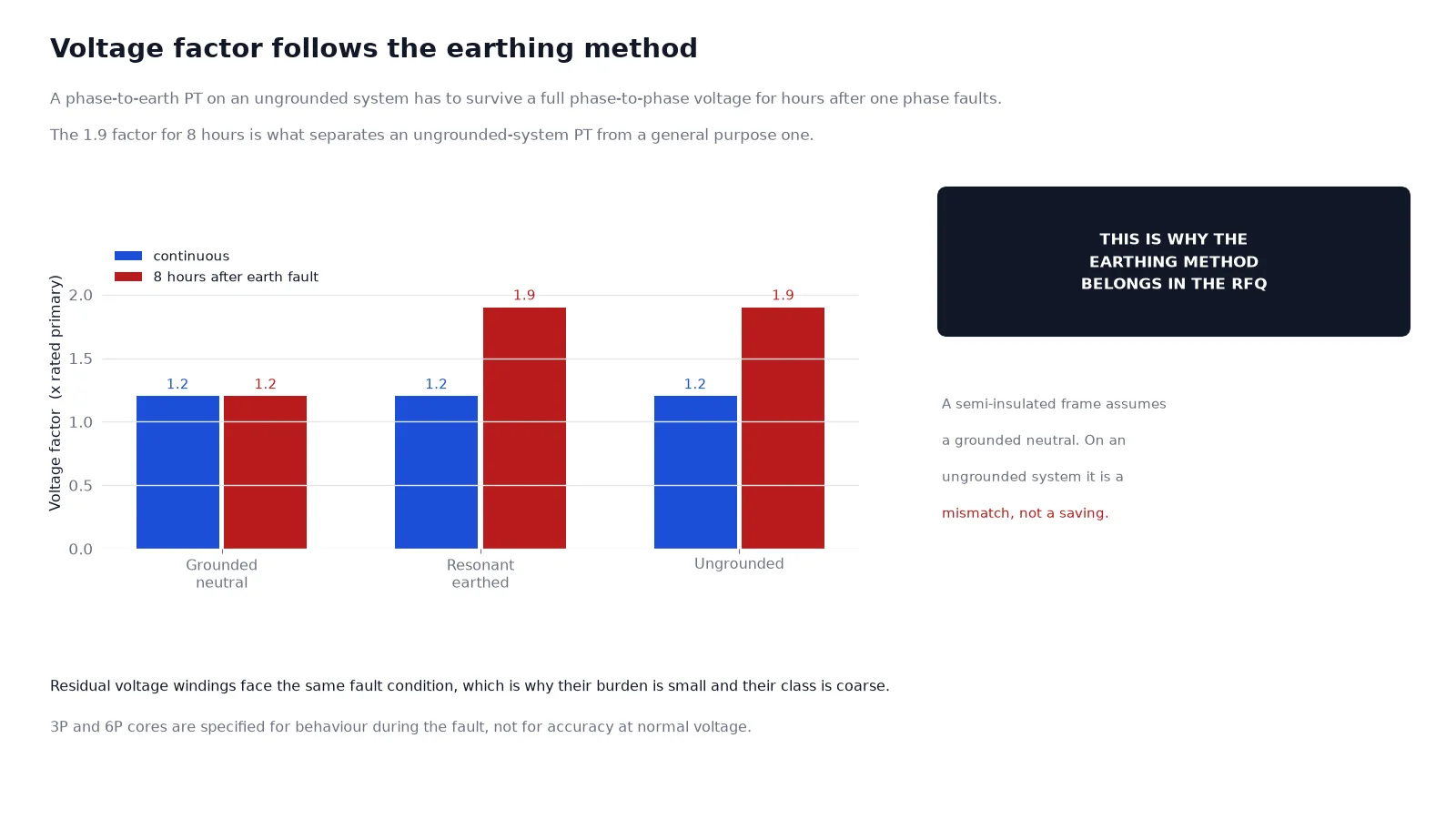
A voltage transformer connected phase-to-earth on a system that is not solidly earthed has to survive a phase-to-phase voltage across its primary for the duration of an earth fault, because the healthy phases rise to full line voltage while the fault persists. IEC 61869-3 expresses this as a voltage factor: 1.2 continuous for a general purpose unit, and 1.2 continuous plus 1.9 for 8 hours for a unit intended for an ungrounded or resonant-earthed system.
That single number is what separates a general purpose PT from one built for an ungrounded network, and it is also the reason a semi-insulated frame is a mismatch on such a system. If you have not yet settled the earthing method, the options and their consequences are set out in medium voltage neutral grounding methods; the PT specification follows from that decision, not the other way round.
Do you need a residual winding?
If the earth-fault protection is a broken-delta relay, yes. A residual winding is a third winding on each unit, connected da to dn, with the three units wired in broken delta. In normal operation the three voltages cancel; during an earth fault they add, and the relay sees a voltage proportional to three times the zero-sequence voltage.
These windings are typically built with a secondary of 100/3 V, about 33 V per winding, so that three of them in broken delta produce roughly 100 V at a full earth fault. Their accuracy class is coarse because they only need to be right at one operating point, but their burden has to match the relay input, and the three units have to come from one production run: mismatched ratios in a broken-delta set produce a standing voltage that either desensitises the relay or makes it chatter.
On a solidly earthed system the residual winding is optional. On an ungrounded or resonant-earthed system it is usually the only way the relay will see an earth fault at all, because the phase-to-phase voltages barely change.
A worked example: 10 kV feeder metering bay
Take a 10 kV feeder with a digital meter, a power transducer and a directional overcurrent relay, in a metal-clad cubicle with about 60 m of 2.5 mm2 secondary cable.
- Connection. Three single-phase units in star, primary star point earthed, plus a residual winding for the earth-fault element.
- Ratio. 5.77 / 0.0577 / 0.0577 kV, giving 100 V line-to-line and about 33 V per residual winding.
- Burden. Meter 3 VA, transducer 8 VA, relay 2 VA – 13 VA before margin. Specify 25 VA rated burden, which sits comfortably inside the class range.
- Class. Metering core 0.5, protection core 3P, residual winding 3P with the burden the relay expects.
- Voltage factor. 1.2 if the neutral is solidly earthed, 1.9 for 8 hours if it is not.
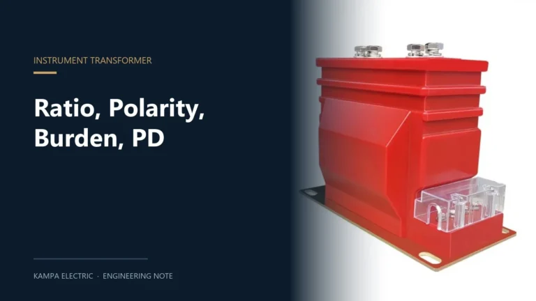
That is a complete specification in five lines, and it is the level of detail that turns a quotation into a confirmed one. The fully insulated frame for exactly this duty is the JDZ10 cast voltage transformer, and where the tap needs its own primary fuse the JDZX18 fused unit is the equivalent frame.
Five mistakes that show up in every second inquiry
- Giving only the system voltage. The ratio depends on the connection, and the insulation depends on Um. Send both.
- Ordering a class without a burden. The class is guaranteed across a burden range; a class with no VA figure cannot be confirmed.
- Connecting open delta and expecting earth-fault measurement. Two units cannot produce a residual voltage.
- Mixing units from different batches into one star or broken-delta set. Small ratio differences become a standing zero-sequence signal.
- Leaving the earthing method out. It decides the voltage factor, and therefore which frame is allowed on the system.
FAQ
What is the standard secondary voltage of a voltage transformer?
100 V line-to-line, or 110 V where the system nominal is 11 kV or the metering is built around 110 V. Phase-to-earth units use 100 divided by root 3, about 57.7 V, so that three in star give 100 V.
Can I use a 10/0.1 kV unit on a 10 kV system with an earthed neutral?
Only if it is connected phase-to-phase. In a star connection with an earthed primary star point, the unit sees 5.77 kV and a 10 kV primary winding would give a secondary reading about 1.7 times too low.
What does the P in 3P mean?
Protection. The 3 or 6 is the permitted composite error as a percentage during a fault, not an accuracy figure at normal voltage. Protection cores are specified for behaviour during faults.
How much burden margin should I leave?
Enough to stay inside the rated value with the full device list, and ideally one standard step above it. The step sizes are 10, 15, 20, 25, 30, 50 and 100 VA.
Does a higher accuracy class fix a voltage drop problem in the leads?
No. Lead resistance is outside the transformer, so its error adds to the transformer’s. Fix it with a larger cross-section, a shorter route, or by moving the meter.
Is a residual winding the same as a third harmonic winding?
No. A residual winding is a full three-phase set in broken delta for earth-fault detection. A third harmonic or auxiliary winding serves a different purpose, usually a damper or a specific relay input, and it is not a substitute.
Next step
Write the five lines from the worked example – connection, ratio, burden, class, voltage factor – and add the system voltage, Um, the earthing method, the pollution level and the altitude. That is a specification a factory can build against without a follow-up question, and it is the shortest path from a request to a confirmed ratio, class and burden in one reply.