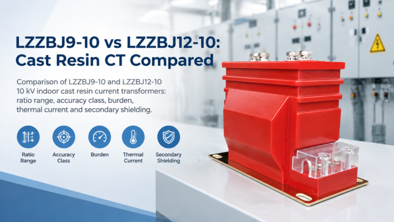
LZZBJ9-10 vs LZZBJ12-10: Cast Resin CT Compared
Both are 10 kV cast resin CTs, but LZZBJ9-10 is 50 Hz only while LZZBJ12-10 covers 50/60 Hz with shielded terminals. Compare before ordering.
Read More

A 35 kV oil-immersed distribution transformer sits between a sub-transmission network and a 400 V distribution board, and that position defines everything about it: the voltage class is fixed by the network, the capacity is fixed by downstream load, and the losses are fixed by how seriously the buyer treats 25 years of energy cost. Get any of the three wrong and the unit is either oversized, under-cooled or economically indefensible.
This guide works through the selection in the order it actually happens — capacity, voltage ratio and taps, losses and total cost of ownership, impedance, cooling and mechanical configuration — using the published 35 kV data table. For the wider context, the oil-immersed power transformer range shows the adjacent voltage classes; if you are still deciding between oil and dry type, start with the oil-immersed transformer selection overview.
The published table lists a high-voltage side of 35 kV or 38.5 kV, with a low-voltage side of 0.4 kV. That dual high-voltage rating is not decoration: 35 kV matches nominal 35 kV networks, and 38.5 kV gives the margin used where the network runs above nominal or where the tap range must reach further. The published tap range is ±5% and ±2 × 2.5%, so a 38.5 kV unit with five tap positions can be set to match the actual busbar voltage at commissioning.
It is also worth saying what 35 kV is in market terms. In much of Asia, Africa and Latin America, 33 kV and 35 kV are the standard medium-voltage distribution levels; in North America the equivalent is 34.5 kV. A 35/38.5 kV transformer therefore covers 33 kV, 35 kV and 34.5 kV networks depending on tap setting and the specified insulation level, which is why one catalogue page serves several regions. The same logic applies one level down, where the 10 kV, 11 kV and 13.8 kV class comparison explains why neighbouring markets publish different nominal voltages for what looks like the same network. Confirm the insulation level explicitly: a 35 kV class liquid-immersed unit typically carries a 200 kV lightning impulse level with a power-frequency withstand in the region of 95 kV at the 40.5 kV maximum system voltage, and that is the figure the local standard will be checked against.
The published range runs from 50 kVA to 2,000 kVA in the standard steps: 50, 100, 125, 160, 200, 250, 315, 400, 500, 630, 800, 1,000, 1,250 and 2,000 kVA. Select from calculated demand, not from a rule of thumb:
Two constraints push the answer upward regardless of the arithmetic. Impedance limits the fault level the LV switchboard has to withstand, and cooling margin limits how long the unit can carry overload. Both are handled below.
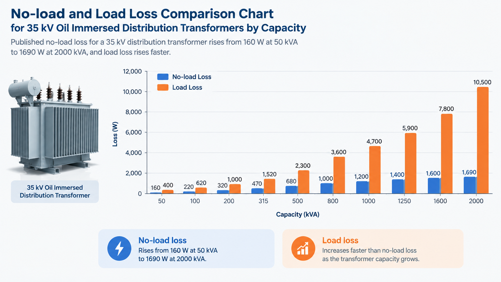
This is the part of a 35 kV transformer specification that most purchase orders get wrong, because the losses are invisible on the invoice and enormous over the asset life. The published table gives no-load loss and load loss for every rating:
| Capacity (kVA) | No-load loss P0 (W) | Load loss Pk (W) | Impedance uk (%) | No-load current (%) | Total weight (kg) |
|---|---|---|---|---|---|
| 50 | 160 | 1,200 / 1,140 | 6.5 | 1.3 | 860 |
| 100 | 230 | 2,010 / 1,910 | 6.5 | 1.1 | 1,130 |
| 160 | 280 | 2,820 / 2,680 | 6.5 | 1.0 | 1,475 |
| 250 | 400 | 3,950 / 2,760 | 6.5 | 0.95 | 2,000 |
| 400 | 580 | 5,740 | 6.5 | 0.55 | 2,725 |
| 630 | 830 | 7,860 | 6.5 | 0.65 | 3,810 |
| 800 | 980 | 9,400 | 6.5 | 0.55 | 4,510 |
| 1,000 | 1,150 | 11,500 | 6.5 | 0.60 | 5,055 |
| 1,250 | 1,900 | 13,900 | 6.5 | 0.60 | 5,450 |
| 2,000 | 1,690 | 16,600 | 6.5 | 0.60 | 5,450 |
To turn those watts into money, capitalise them. The standard total-cost-of-ownership form is:
TCO = purchase price + A × P0 + B × Pk, where A = annuity factor × energy price × 8,760 and B = A × load factor².
At 8% discount rate, 25 years and USD 0.12/kWh, the annuity factor is 10.675, so A works out to about USD 11.2 per watt of no-load loss — no-load loss runs 8,760 hours a year. Load loss is capitalised at the same rate multiplied by the square of the load factor, so at 70% loading B is about USD 5.5 per watt.
Run that on the 630 kVA row: 830 W × 11.2 = roughly USD 9,300 of capitalised no-load loss, and 7,860 W × 5.5 = roughly USD 43,000 of capitalised load loss. A lower-loss design that cuts load loss by 10% is worth about USD 4,300 in present value — often more than the price difference between two suppliers. That is the entire argument for specifying an efficiency level rather than accepting the catalogue default, and it is why the published table above should be checked against the efficiency regulation of the destination market.
Note also the load point at which efficiency peaks. For medium-voltage liquid-immersed transformers the reference load point used in efficiency standards is 50% of rating, not the 35% used for low-voltage dry-type units. Comparing an efficiency figure quoted at one load point with a figure quoted at another is a common and expensive mistake.
The published impedance is 6.5% for the whole range. Impedance does two jobs at once: it limits the LV fault current the downstream switchboard must withstand, and it sets the voltage dip when a large motor starts.
A lower impedance gives a stiffer supply and better motor starting, but a higher LV fault level. A higher impedance reduces the fault level and allows a cheaper LV board, but produces deeper voltage dips and more flicker. On a 35/0.4 kV unit the 6.5% figure is a reasonable compromise for general distribution; where the LV board is being designed at the same time, run both cases and let the fault study choose.
Oil-immersed distribution transformers are normally supplied with ONAN cooling — oil natural, air natural — which needs no fans and no auxiliary supply. The published temperature rise for this class of unit is 55 K for oil and 55 K for windings, and that figure is what defines the permitted overload.
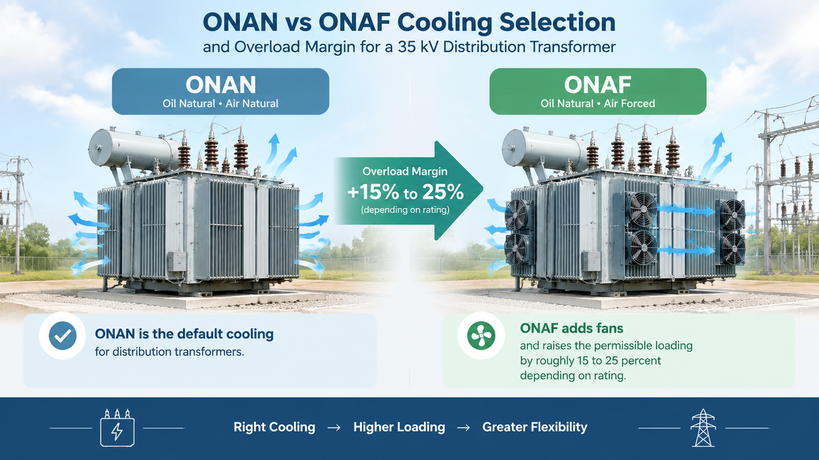
ONAF cooling adds fans and raises the permissible loading further, but on distribution sizes the gain is modest and the fans become a maintenance item and a single point of failure. Two practical positions:
Ambient temperature is the other half of that calculation. A unit rated at 55 K rise in a 40 °C ambient derates in a 50 °C environment, and the derating has to be applied to the capacity, not just noted on the datasheet. Where the load is expected to vary across the day and the year, the tap changer arrangement and the voltage regulation question are covered in the off-circuit versus on-load tap changer comparison.
| Item | Typical 35 kV distribution choice | What it affects |
|---|---|---|
| Vector group | Dyn11 | Harmonic behaviour, earth-fault current, parallel operation |
| High-voltage connection | Cable box or overhead bushings | Substation layout, cable termination cost |
| Tap changer | Off-circuit, ±2 × 2.5% | Commissioning adjustment only, no live change |
| Cooling | ONAN | Maintenance load, auxiliary supply |
| Oil preservation | Sealed tank with conservator or hermetic | Oil ageing, inspection interval |
| Protection devices | Buchholz relay, pressure relief, oil temperature and winding temperature indicators | Fault detection and insurance compliance |
| Enclosure | None, or a lockable enclosure for public sites | Safety clearance and access control |
If the transformer will run in parallel with an existing unit, the vector group, impedance and tap range must all match, not just the capacity and ratio. Parallel units with different impedance share load in inverse proportion to it, and a 6.5% unit beside a 4% unit will carry far more than half the load and trip first.
| Mistake | Result | Fix |
|---|---|---|
| Sizing from connected load with no demand factor | Unit two steps oversized; capitalised no-load loss paid for 25 years | Apply the demand factor, then add a growth allowance |
| Buying on purchase price alone | Higher losses cost more than the price saving within a few years | Capitalise P0 and Pk with the TCO formula |
| Comparing efficiency at different load points | Wrong unit selected on paper | Confirm both figures are at 50% load for MV liquid-immersed units |
| Assuming forced cooling covers a capacity shortfall | No margin left for ambient peaks; fan failure becomes a load drop | Size for ONAN firm capacity |
| Ignoring the LV fault level | Downstream switchboard under-rated for the impedance chosen | Run the fault study with the specified uk |
| Ordering 35 kV for a 33 kV network without checking taps | Voltage at the LV bus cannot be brought into range | Specify 38.5 kV or confirm the tap range covers 33 kV |
Selection starts with capacity, but the decision that saves or costs the most money is the loss specification. A 35 kV distribution transformer runs continuously for decades; a few hundred watts of no-load loss and a tonne of load loss, capitalised at USD 11 per watt, dwarf the difference between quotations. Fix the capacity from a demand calculation, fix the ratio and taps from the actual network voltage, then specify losses deliberately rather than accepting whatever the catalogue prints.
The published data for the whole 50 to 2,000 kVA range is on the 35 kV oil-immersed distribution transformer page, and the cost breakdown for oil-immersed transformers explains how capacity, losses, accessories and destination market requirements move the price. If the project is a substation package rather than a single unit, the 30 kV substation transformer case shows how the auxiliary and protection scope is normally bundled.
It steps a 35 kV (or 33 kV, or 34.5 kV) sub-transmission or distribution voltage down to 0.4 kV for industrial plants, commercial buildings, infrastructure and local distribution. The published range covers 50 kVA to 2,000 kVA with a 6.5% impedance and a 0.4 kV low-voltage side.
Match the network. Use 35 kV on nominal 35 kV networks where the busbar voltage stays near nominal, and 38.5 kV where the network runs high or the tap range must reach further. With ±5% and ±2 × 2.5% taps, the 38.5 kV rating gives more room at commissioning.
No-load loss is the iron loss, present whenever the transformer is energised, and it runs 8,760 hours a year. Load loss is the copper loss, proportional to the square of the load, and it is zero at no load. No-load loss dominates the capitalised cost for a lightly loaded unit; load loss dominates above about 50% loading.
It balances two competing needs: keeping the LV fault current within the withstand rating of standard 0.4 kV switchgear, and keeping the voltage dip during motor starting acceptable. A lower impedance would let the LV board see higher fault current; a higher one would deepen starting dips.
Yes, oil-immersed distribution transformers are normally designed for outdoor installation with weatherproof bushings and a sealed or conservator tank. An enclosure is usually added for public-access sites, where safety clearance cannot be guaranteed by fencing alone.
ONAN is the standard, with no fans and no auxiliary supply. ONAF is available where extra capacity is needed from the same frame, but on distribution ratings it adds a maintenance item and a dependency on fan availability, so most buyers prefer the next size up in ONAN instead.